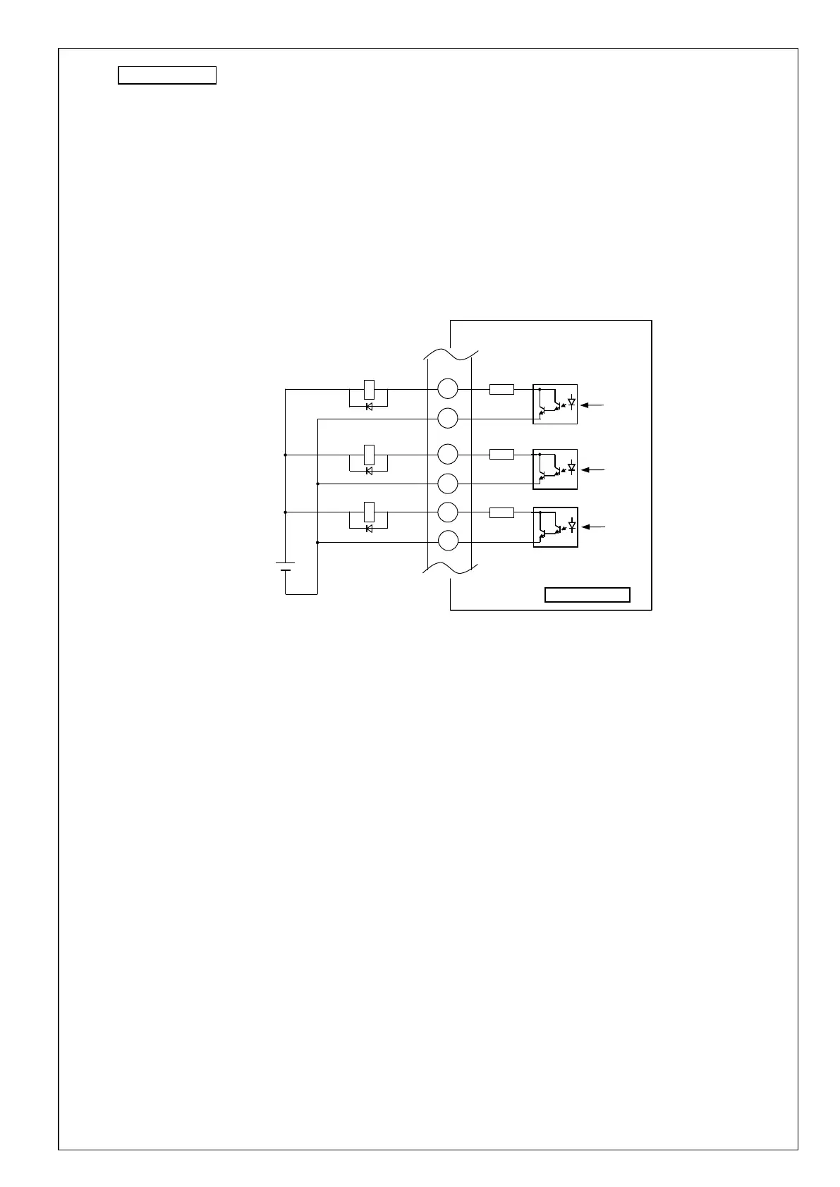
Control output
[1] Be aware of the polarity of the power supply for control signals.
The polarity connection contrary to the figure shown above can damage the servo driver.
[2] To directly drive the relay with each output signal, make sure to install a diode in parallel to the relay and in
the direction as shown in the figure below. If a diode is not installed or it is installed in the reverse direction,
the servo driver may be damaged.
[3] When receiving each output signal by a logic circuit such as a gate, be careful not to be affected by noise.
[4] The current to be passed through each output should be rated current 40 mA, maximum current 50 mA,
inrush current 90 mA or less.
[5] Limiting resistance (10 Ω) is connected to the output circuit.
Also, since the output transistor is a Darlington connection, the collector-emitter voltage VCE (SAT)
at the time of transistor ON is about 1 V, and since VIL can not be satisfied with a normal TTL IC
Please be aware that it can not be connected directly.
Functions SO1 to SO3 should be allocated by parameters.
For details, refer to "Technical Reference -Functional Specification-".