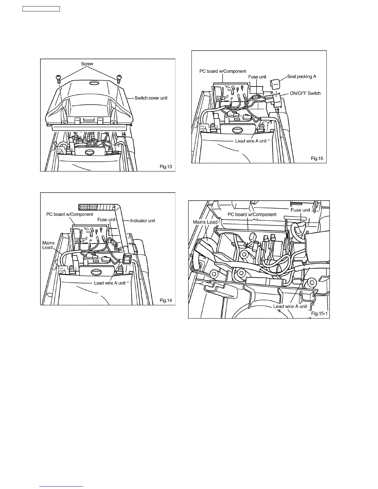
1. Loosen two screws from the switch cover unit and take it
out.(Fig. 12)
2. Take out the indicator unit . (Fig 13.)
3. Lift the PC board w/component, and disconnect the Faston
terminals and connectors of the lead wires. (Fig 14.)
4. Detach the seal packing A, and disconnect the Faston
terminals of the lead wires. (Fig 15.)
Note: The ON/OFF Switch, Fuse unit and Mains lead
(power cord) can be removed at once.
5. Connect the lead wires according to the schematic diagram
and re-install switch cover refastening the screws.
* Connection of lead wire during assembly
Connect lead wire as shown in Fig. 15-1.
Make sure that the mains lead (power cord) and lead
wire A unit are set in the clearance between the ribs.
4.6. PC board w/component, ON/OFF Switch, Fuse unit and Mains lead
(power cord)
10
MC-E3001 / MC-E3003