- 28 -
8.2 Door Lock Switch
NA-FS80X1 / FS90X1
Illustration Disassembly Procedure
Panel sheet A
Door lock switch
Controller display
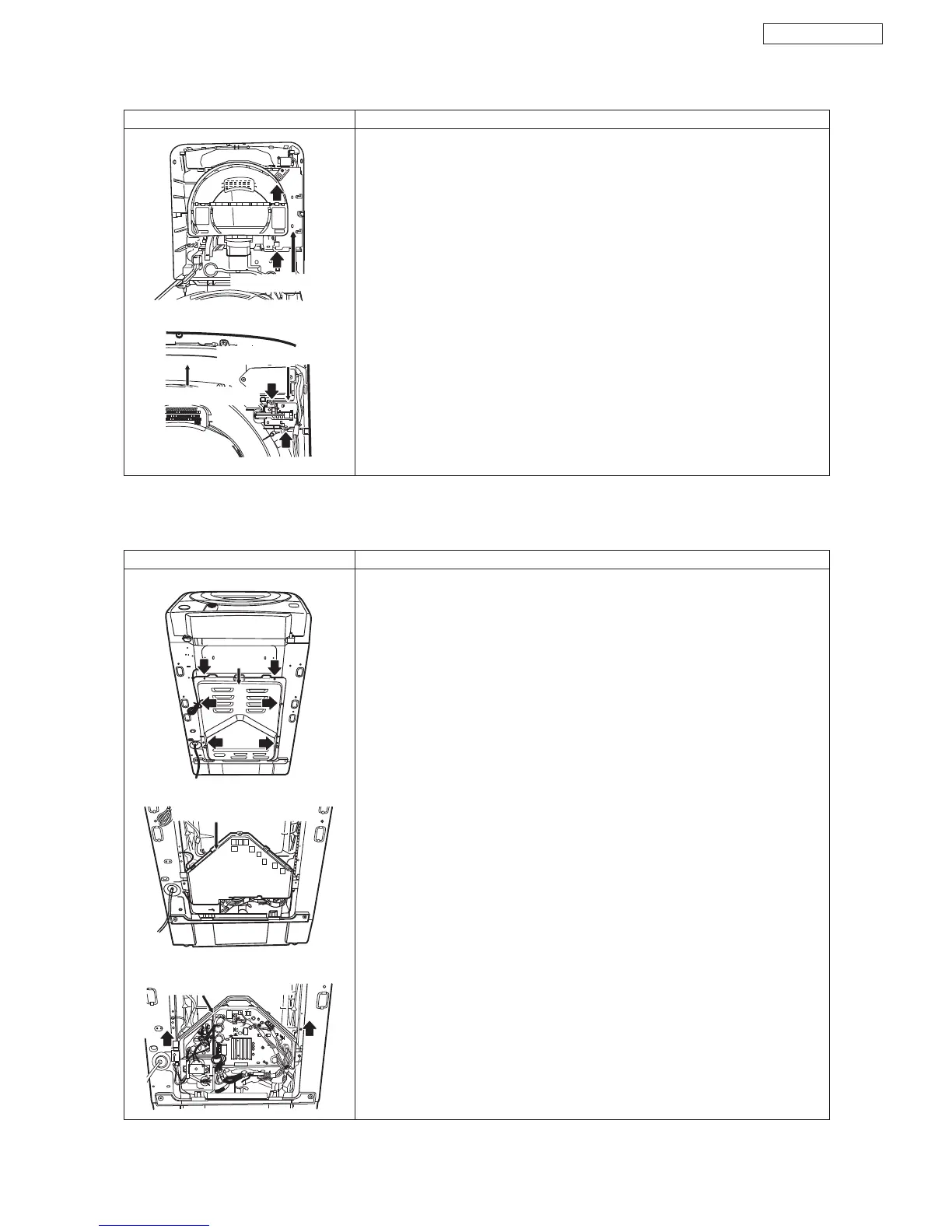
8.3 Load Controller
Illustration
Controller case cover
Back panel
Controller (loading)
Disassembly Procedure
●
Necessary tool plus driver
●
Replacement for load controller
(1) Take off back panel installation screw (6 pieces)
(2) Take off controller case cover (7 places of hook)
(3)
Take off controller connector and ground wire installation screw (2 pieces).
Then lift and slide controller unit (fixing with hook at right and left side)
to remove.
※
Light blue 6 pin connector is no use
●
Necessary tool plus driver
●
Replacement of door lock switch
(1) Refer to procedure (1) to (4) [replacement for controller display].
(5) Take off panel A sheet (2 screws)
(6) Take off door lock, switch installation screw (2 pieces).
(7) Take off the connector of the door lock, switch and replace it.
 Loading...