Do you have a question about the Panasonic NN-GD577M and is the answer not in the manual?
Electrical schematic for the NN-GD577M and NN-GT547W models.
Electrical schematic for the NN-SD577M model.
Crucial checks for grounding, inverter high voltage, and capacitor discharge procedures.
Guidelines for part replacement, fuse issues, avoiding object insertion, and sharp edges.
Confirming repairs, checking for leaks, and precautions against microwave radiation exposure.
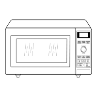
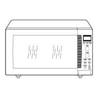
Visual representation of microwave oven components for identification.
Comprehensive list of all replacement parts with part numbers and specifications.
Identifies lead wire harnesses and their connections for the microwave oven's electrical system.
Lists for door assembly and High Voltage Inverter unit components.
Components for the escutcheon base assembly of GD577M and SD577M models.
Components for the escutcheon base assembly of the NN-GT547W model.
List of items included in the product packaging and how they are packed.
Detailed circuit diagram for the digital programmer control unit of specific models.
Detailed circuit diagram for the digital programmer control unit of the NN-GT547W model.
Specific parts list for components within the digital programmer circuit.
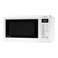
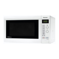
This document is a service manual for Panasonic Microwave Ovens, specifically models NN-GD577M, NN-SD577M, and NN-GT547W. It provides comprehensive information for trained and qualified repair technicians, covering the device's function, usage, and maintenance features, with a strong emphasis on safety protocols due to the high voltage and high current nature of microwave ovens.
The Panasonic Microwave Oven is designed for heating and cooking food using microwave energy. The core of its operation involves a magnetron tube, which generates microwaves, and an inverter power supply (U) that drives the magnetron. Unlike conventional microwave ovens that use a high voltage transformer and capacitor, these models utilize an inverter board, which is a PCB (Printed Circuit Board) that generates extremely high voltage and high current to power the magnetron. This inverter board functions similarly to the traditional high voltage components but with a different internal architecture.
The oven incorporates a digital programmer circuit, which manages various cooking functions and settings. This circuit interfaces with user controls, such as buttons and dials, to allow for precise control over cooking time, power levels, and specialized cooking modes. The schematic diagrams provided in the manual detail the intricate connections and components within this digital programmer, including the main LSI (Large Scale Integration) chip, memory, and interface circuits for the display and input devices.
Specific models like the NN-GD577M also feature a steam sensor, indicating advanced cooking capabilities related to steam-based cooking. The oven cavity is designed to contain microwave energy, ensuring efficient heating and preventing leakage. Safety interlock switches are integrated into the door mechanism to prevent microwave generation when the door is open, a critical safety feature.
While this manual is primarily for service, it implicitly describes usage features through the components and circuits. The digital programmer circuit allows users to select various cooking programs, indicated by the "MENU SHEET" on the escutcheon base assembly. The presence of "COOK BUTTON SPRING" and "POP-UP DIAL" suggests an intuitive user interface for setting cooking parameters.
The inclusion of a "TURN TABLE MOTOR" indicates that the oven utilizes a rotating turntable to ensure even heating of food. The "OVEN LAMP" provides illumination inside the cavity, allowing users to monitor the cooking process. The "FAN MOTOR" is essential for cooling the magnetron and other internal components during operation, preventing overheating.
The oven's design includes a door assembly with a "DOOR KEY" and "DOOR KEY SPRING," which are part of the latching mechanism. The "DOOR SCREEN" is a critical component that allows visibility into the oven while blocking microwave radiation. The "OVEN RACK" and "COOKING TRAY" are standard accessories for placing food inside the oven.
The manual provides extensive guidance on maintenance and repair, with a strong emphasis on safety. Key maintenance features and considerations include:
The manual also includes detailed exploded views and parts lists for various assemblies, such as the door assembly, H.V. inverter main parts, and escutcheon base assembly, facilitating accurate identification and ordering of replacement parts. Wiring diagrams are provided to guide technicians in correctly connecting components.
| Grill Power | 1000 W |
|---|---|
| Microwave Power Levels | 5 |
| Turntable | Yes |
| Inverter Technology | Yes |
| Turntable Diameter | 315 mm |
| Grill | Yes |
| Convection | Yes |
| Color | Silver |
| Capacity | 27 liters |
| Power Output | 900 Watts |
| Microwave Power | 900 Watts |
| Control Type | Digital |
| Type | Microwave Oven with Grill and Convection |