EasyManua.ls Logo

Panasonic NN-SD291S - User Manual

Panasonic NN-SD291S
26 pages
Print Icon
To Next Page IconTo Next Page
Loading...
© Panasonic Home Appliances Microwave Oven
(Shanghai) Co., Ltd. 2011.
NN-SD291S
NN-SD291W
CPH(CANADA)
Microwave Oven
Please file and use this manual together with the service manual for Model NN-S262SF (Order
No.SIMMC0203005C1)
ORDER NO.PHAMOS1106067AE
E2
Question and Answer IconNeed help?

Do you have a question about the Panasonic NN-SD291S and is the answer not in the manual?

Summary

Specifications

PRECAUTIONS TO BE OBSERVED BEFORE AND DURING SERVICING TO AVOID POSSIBLE EXPOSURE TO EXCESSIVE MICROWAVE ENERGY

DANGER OF HIGH VOLTAGE AND HIGH TEMPERATURE (HOT;LIVE) OF THE INVERTER POWER SUPPLY (U)

1 SCHEMATIC DIAGRAM

2 DESCRIPTION OF OPERATING SEQUENCE

2.1. Variable power cooking control

Explains how the High Voltage Inverter Power Supply controls output power via PWM signals.

2.2. Inverter power supply circuit

Details the function of the Inverter Power Supply circuit, including voltage conversion for the magnetron.

2.3. Inverter defrost

Describes the Auto Control feature for inverter defrost and its operation sequence.

2.4. Sensor cooking

Explains Auto Sensor Cooking, using a humidity sensor to detect steam for automatic cooking.

2.5. Sensor reheat

3 CAUTIONS TO BE OBSERVED WHEN TROUBLESHOOTING

3.1. Check the grounding

Emphasizes the importance of proper grounding for microwave oven safety during repair.

3.2. Inverter warnings

Highlights high voltage and temperature hazards associated with the Inverter Power Supply.

3.3. Part replacement.

3.4. When the 20 A fuse is blown due to the malfunction of the monitor interlock switch:

Details troubleshooting steps when the 20A fuse blows, involving interlock switches and power relay.

3.5. Avoid inserting nails, wire etc. through any holes in the unit during operation.

Warns against inserting metal objects into the oven, which can cause microwave leakage.

3.6. Verification after repair

Outlines checks required after repair, including screw tightness, connections, and leakage.

3.7. Sharp edges

Advises caution due to sharp edges on internal parts during disassembly and reassembly.

4 COMPONENT TEST PROCEDURE

4.1. Primary, Secondary Interlock Switch & Power Relay RY1

Details continuity testing procedures for interlock switches and power relay RY1.

4.2. Monitor Switch

Explains how to test the continuity of the monitor switch with the door in different positions.

4.3. Magnetron

Describes continuity checks for the magnetron filament and case to diagnose faults.

4.4. Inverter power supply (U)

4.5. Humidity sensor

Provides a test procedure to verify the function of the humidity sensor in the digital programmer circuit.

5 MEASUREMENTS AND ADJUSTMENTS

5.1. Adjustment of primary interlock switch, secondary interlock switch and monitor switch.

Details mounting and adjusting interlock and monitor switches to the door hook assembly.

5.2. Measurement of microwave output

Outlines a simple method for measuring microwave output power using water temperature rise.

6 PROCEDURE FOR MEASURING MICROWAVE ENERGY LEAKAGE

6.1. Equipment

Lists the necessary equipment for measuring microwave radiation leakage.

6.2. Procedure for measuring radiation leakage

Details the step-by-step process for measuring microwave radiation leakage.

6.2.1. Measurement with the outer panel removed.

Explains leakage measurement after replacing the magnetron with the outer panel removed.

6.2.2. Measurements with a fully assembled oven.

Describes leakage measurements on a fully assembled oven, checking door periphery and openings.

6.3. Record keeping and notification after measurement

Specifies requirements for recording leakage readings and notifying authorities if limits are exceeded.

6.4. At least once a year, have the radiation monitor checked for calibration by its manufacturer.

7 TROUBLESHOOTING GUIDE

7.1. Troubleshooting of inverter circuit (U) and magnetron

Provides failure codes (H95, H97, H98, H99) and troubleshooting steps for inverter and magnetron issues.

7.2. SIMPLE WAY OF H.V. INVERTER;MAGNETRON TROUBLESHOOTING

7.3. H.V.INVERTER BOARD MAIN PARTS LIST (F606 Y8 X00 AP)

Lists main parts of the H.V. Inverter Board for identification and replacement.

8 EXPLODED VIEW AND PARTS LIST

8.1. EXPLODED VIEW

Provides a visual exploded view of the oven assembly with numbered parts.

8.2. PARTS LIST

Lists replacement parts with reference numbers, part numbers, descriptions, and quantities.

8.3. DOOR ASSEMBLY

Details the components and parts list for the oven's door assembly.

8.4. ESCUTCHEON BASE ASSEMBLY

Lists the parts and components for the escutcheon base assembly, including the control panel.

8.5. PACKING AND ACCESSORIES

Details the items included with the oven and the packing procedure for accessories.

8.6. WIRING MATERIALS

Lists and describes the various lead wire harnesses used in the microwave oven.

9 DIGITAL PROGRAMMER CIRCUIT

9.1. SCHEMATIC DIAGRAM

Presents the detailed schematic diagram for the Digital Programmer Circuit.

9.2. PARTS LIST

Provides a parts list for components related to the Digital Programmer Circuit.

Overview

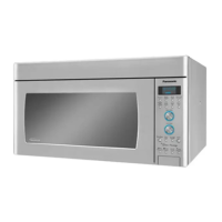
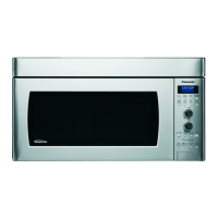
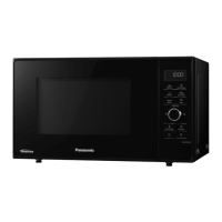
This document is a service manual for the Panasonic NN-SD291S and NN-SD291W Microwave Ovens, identified by order number PHAMOS1106067AE. It provides comprehensive information for servicing, troubleshooting, and maintaining these models.

The microwave ovens operate on a 120V AC single-phase, 60Hz power source, with a power requirement of 1440W and an output of 1100W. They utilize a microwave frequency of 2450MHz. The external dimensions are 29 7/8" (W) x 15 1/2" (D) x 16 7/16" (H) or 759mm (W) x 393mm (D) x 418mm (H). The oven cavity dimensions are 23 1/4" (W) x 14 7/16" (D) x 9 1/2" (H) or 591mm (W) x 367mm (D) x 242mm (H). The approximate weight is 55 lbs (25.0 Kg). These models are PbF (lead-free) compliant.

Function Description:

The microwave ovens feature variable power cooking control, managed by a Digital Programmer Circuit (DPC) that sends a Pulse Width Modulation (PWM) signal to the High Voltage Inverter Power Supply (U). This inverter circuit, unlike traditional microwave transformers, capacitors, and diodes, directly supplies 4,000V DC to the magnetron tube. The output power of the magnetron is continuously monitored by a current transformer within the inverter circuit, providing feedback to the DPC for precise power control.

The ovens offer various cooking settings:

  • High (P10-P8): 100% to 80% output power.
  • Medium-High (P7): 70% output power.
  • Medium (P6-P4): 60% to 40% output power.
  • Medium-Low (P3-P2): 30% to 20% output power.
  • Defrost (P3): 30% output power.

A key feature is the "Inverter Turbo Defrost," which automatically determines cooking time based on selected weight (e.g., 1.0 LB defrosts in 5 min. 28 sec.).

Usage Features:

The models incorporate "Auto Sensor Cooking" and "Sensor Reheat" functions. These features allow the oven to automatically determine the correct power level and cooking time without manual input. A humidity sensor element detects steam escaping from food, and the microprocessor calculates the remaining cooking time (T2 time) based on an initial T1 time and a K factor. The K factor varies with "More" or "Less" button selections. For example, in Oatmeal mode, if T1 is 2 minutes 40 seconds, T2 would be 16 seconds (160 sec * 0.1). Sensor Reheat is a quick and easy way to reheat refrigerated and room temperature foods, requiring only a button press.

Maintenance Features:

The manual emphasizes safety precautions during servicing, particularly regarding the high voltage and high current circuits of the Inverter Power Supply (U). Servicing should only be performed by trained, qualified personnel.

Safety Warnings:

  • High Voltage: The inverter board, magnetron, high voltage transformer, diodes, and capacitors operate at potentials above 2000V. The aluminum heat sink is also energized with high voltage and heat. Extreme caution is required to avoid electric shock or burns.
  • Discharging Capacitors: Always unplug the power cord and discharge high voltage capacitors by shorting the magnetron filament terminals to chassis ground with an insulated screwdriver for about 30 seconds after the oven is turned off.
  • Grounding: Ensure proper grounding of the appliance and the inverter circuit board.
  • Radiation Leakage: Check for microwave energy leakage before and after servicing, especially after replacing radiation safety devices or components like the magnetron or door hinges. Leakage should be less than 2 mW/cm² (1mW/cm² for Canada) for a fully assembled oven.
  • Part Replacement: Critical parts marked with a triangle symbol must be replaced only with manufacturer-specified parts to prevent hazards.
  • Fuse Replacement: If the 20A fuse blows due to a monitor interlock switch malfunction, replace the primary interlock switch, monitor switch, and power relay RY1 simultaneously.
  • Sharp Edges: Exercise caution when disassembling or reassembling internal parts due to sharp edges.

Troubleshooting:

The oven includes a self-diagnostics failure code system (H95, H97, H98, H99) to indicate magnetron and inverter circuit problems. The manual provides a flowchart for troubleshooting these codes, including checks for magnetron filament continuity, inverter input AC voltages, and inverter control signals.

Inverter Power Supply (U) Repair:

The manual explicitly states: "DO NOT try to REPAIR H.V. Inverter power supply (U). Replace complete H.V. Inverter(U) Unit." This is due to the extreme danger associated with repairing these high voltage, high current circuits without proper test equipment. Defective inverter boards must be replaced with new ones.

Component Testing:

Procedures are outlined for testing:

  • Primary, Secondary Interlock Switch & Power Relay RY1: Continuity checks with the door opened and closed.
  • Monitor Switch: Continuity checks with the door opened and closed.
  • Magnetron: Continuity checks for filament (should be 1 ohm or less) and between filament terminals and case (should be open).
  • Inverter Power Supply (U): Tests involve unplugging connectors and observing oven behavior and input current to identify failure codes (H95, H97, H98).
  • Humidity Sensor: A test procedure involving a water load and observing cooking time in the display window.

Measurements and Adjustments:

  • Interlock Switches: Adjustment of primary, secondary, and monitor switches involves mounting them correctly to the door hook assembly and ensuring smooth movement of interlock keys.
  • Microwave Output: A simple method using a 1-liter beaker of water, a thermometer, and a stopwatch is provided to measure temperature rise after 1 minute of high power cooking. For an 1100W rated output, a minimum temperature rise of 16.9°F (9.4°C) is expected.
  • Radiation Leakage: Detailed procedures for measuring radiation leakage with and without the outer panel, and around the door periphery, viewing window, exhaust opening, control panel, and air inlet openings. A radiation monitor should be checked for calibration annually.

The manual also includes exploded views, parts lists (including lead-free solder PCBs indicated by "PbF" stamp), and schematic diagrams for the digital programmer circuit and wiring materials. It notes that PbF solder has a higher melting point (30-40°C higher than standard solder) and requires a high-temperature soldering iron (370 ± 10°C), with eye protection recommended due to splashing.

Panasonic NN-SD291S Specifications

General IconGeneral
BrandPanasonic
ModelNN-SD291S
CategoryMicrowave Oven
LanguageEnglish

Related product manuals