NR-BY558/NR-BY55B/NR-BY608
CONTENT
1. SAFETY CAUTIONS FOR REPAIRING 3
1.1 Warning
1.2 Cautions
2. SPECIFICATION AND COMPONENTS
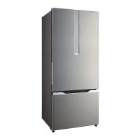
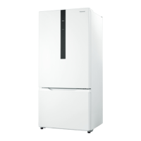
2.1 NR-BY558XS, PS/NR-BY55BPS, VW 4
2.2 NR-BY608PS, XS 5
3. PERFORMANCE DATA 6
3.1 NR-BY55BPS, NR-BY55BVW, NR-BY558PS (AT 32±1 °C)
3.2 NR-BY558XS (AT 32±1 °C)
3.3 NR-BY608PS (AT 32±1 °C)
3.4 NR-BY608XS (AT 32±1 °C)
4. DISPLAY SPECIFICATION 7
5. SELF PROTECTING FUNCTION 8
5.1 Protection for IC
5.2 Protection for compressor locked 9
5.3 Protection for power supply droping 10
6. SELF DIAGNOSING FUNCTION 11
7. TEMPERATURE CONTROL 12
7.1 Temperature control NR-BY558XS/NR-BY608XS
7.2 Temperature control NR-BY558PS/NR-BY608PS
7.3 Temperature Control (Find Adjustment Mode) 13
8. OPERATION 14
8.1 Quick freezing
8.2 ECONAVI Operation
9. REFRIGERATOR INSRUCTION GUIDELINE 15
10. TROUBLESHOOTING GUIDE 16
10.1 Not cool at all [ Both PC & FC (compressor does not operate) ]
10.2 Cool, not enough [ Both PC & FC (compressor operate) ] 17~18
11. ECONAVI OPERATION DOESN'T WORK (PC/FC/IC cooling condition is normal 19
12. SCHEMATIC DIAGRAM
12.1 Wiring diagram : NR-BY558XS, NR-BY608XS 20
12.2 Wiring diagram : NR-BY558PS, NR-BY55BPS, NR-BY55BVW, NR-BY608PS 21
13. DISASSEMBLY INSTRUCTION 22
13.1 LED PCB and Cover LED lamp position
13.2 Cover LED lamp
13.3 PAS-OPERATION PCB (DOOR) FOR X TYPE 23
13.4 PAS-OPERATION PCB (DOOR) FOR X TYPE 24
13.5 PAS-OPERATION PCB (INSIDE) FOR PS, VW TYPE 24
13.6 Plate PF As (X Model) 25
13.7 Fan Motor 25
14. Service information 26
14.1 Dryer set (Kit) R600a
14.2 Insert the D-joint Pipe (Capilary tube into Dryer) 27
14.3 Notes of Wire connected work (Scotch lock) 28
14.4 Temperature control device./P, VW Type. 29
14.5 Phenomenon of defective senser/Thermal fuse. 30
14.6 Start mode/Manual Defrost mode 31
15. Parts Exploded View and Replacement Parts List 32
15.1 Part Exploded View : Body
15.2 Part Exploded View : Door 33
15.3 Part Exploded View : Packing 34
15.4 Replacement Parts List 35~37
Page
- 2 -