No. Item Procedure
1 Confirmation of Tape Running Equipment 1. Mini DV Cassette
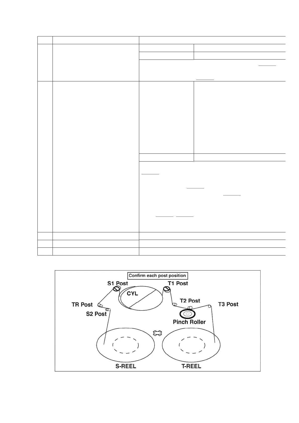
Specification Refer to Fig. 1-1 and Fig. 1-2
1) Confirm each post position in playback mode. (Fig. 1-1)
2) Confirm condition of tape regulation of each post in playb
and review modes. / (Fig. 1-2)
2 Linearity Adjustment Equipment 1. DV Alignment Tape (VFM3110EDS)
2. ENV Detector Board (VFK1641)
3. Mesuring Board (VFK1308E)
4. 232C(M3) I/F Cable (VFK1395)
5. EVR Connector Board (VFK1309)
6. ConnectionAdaptor (VFK1309EX)
7. 30 pin Flat Cable(X2) (VFK1317 or
VFK1511)
8. DC Output Cable (VJA0941)
9. Personal Computer
Specification Refer to Fig. 2-5
1) Connect the cables and boards between camera unit and
(Fig. 2-1)
2) Connect the ENV Detector Board between Mesuring Board
Oscilloscope. / (
Fig. 2-2)
3) Remove the Adjustment Cover. (
Fig. 2-3)
4) Playback the Alignment Tape.
5) Adjust S1 and/or T1 posts by screw driver until waveformi
spec. (Fig. 2-4, Fig. 2-5)
6) After Linearity adjustment, B.E.R. value should be confirm
by using Tatsujin / AdjustmentKit.
3 Sensor Sensitivity Adjustment Refer to Tatsujin Adjustment.
4 Confirmation of B.E.R. Value Refer to Tatsujin Adjustment.
5 Tension Adjustment Refer to TR Band & TR Arm U. assembly section of this manu
Fig. 1-1
Fig. 1-2
29
www.freeservicemanuals.info