4. ASSEMBLY PROCEDURE
No. Item Fig. Oil &
Grease
Procedure
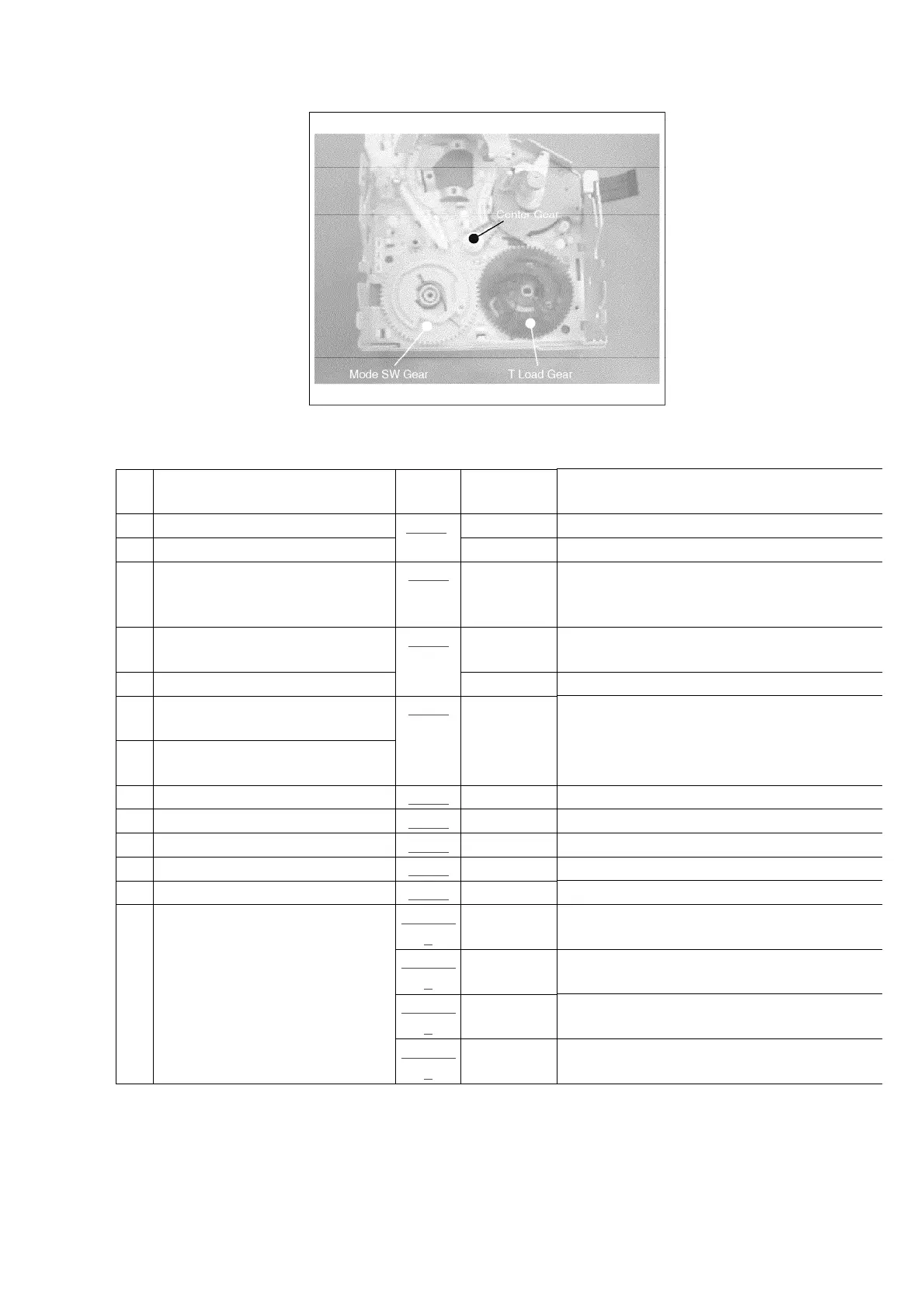
1 Center Gear Fig. 1 - Install Center Gear
2 Mode SW Gear Grease Install Mode SW Gear
3 T Load Gear Fig. 2 Grease Install T-Load Gear so that triangle phase
marks on Mode SW and T Load Gears meet
each other.
4 Rail Fig. 3 - Install Rail and fix it with 5 Locks(W), (X), (
(Z) and (a)
5 Connection Worm Grease Install Connection Worm
6 S-Boat U. & S-Post Loading
Band
Fig. 4 Oil / Grease 1) Install S and T-Boats together with Loadi
Band / 2) Connect S-Loading Band to Mode
and T-Loading Band to / T-Load Gear
7 T-Boat U. & T-Post Loading
Band
8 Brake Gear Fig. 5 - Install Brake Gear
9 TR Rod Fig. 6 - Install TR Rod
10 Loading Motor U. Fig. 7 Grease Install Loading Motor
11 T3 Arm U. Fig. 8 - Install T3 Arm U.
12 Pinch Arm U. Fig. 9 - Install Pinch Arm U.
13 Reel Plate U. Fig. 10-
1
- Confirm Idler position and set it into Reel Pl
U.
Fig. 10-
2
Grease Install Reel Plate U.
Fig. 10-
3
- Fix Reel Plate U. with 11 Locks(I), (J), (K), (L
(M), (N), (O), (P), (Q), (R) and (S)
Fig. 10-
4
- Fix Flex. Cable with 6 Hooks(D)
13
www.freeservicemanuals.info