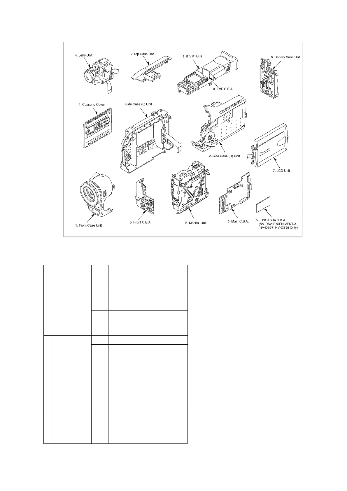
8.2. DISASSEMBLY PROCEDURES
Flow-Chart for Disassembly Procedure
No.
Item/Part Fig. Removal (Screw & Other)
1. Front Case
Unit &
Cassette
Cover
Fig. 1 6-Screws(A/B/C)
Fig. 2 5-Screws(D/E/F)
Fig. 3 6-Screw(G/H/I)
Remove Cassette Cover
Fig. 4 Unlock---(a)
Remove the Front Case
Unit.
2. Side Case
(R) Unit
Fig. 5 5-Screws(J/K/L)
Fig. 6 Slide the Side Case (R)
Unit.
Disconnect the following
connectors.
FP601/FP6302/P4201/
FP3902
Remove the Side Case (R)
Unit.
3. EVF Unit &
Top Case
Unit
Fig. 7 1-Screw(M)Disconnect the
FP801.
Remove the EVF Unit.
Remove the Top Case Unit.
13
www.freeservicemanuals.info