EasyManua.ls Logo

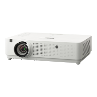
Panasonic PT-VX500U

Panasonic PT-VX500U
129 pages
To Next Page IconTo Next Page
Loading...
Model No. PT-VX500U
PT-VX500E
PT-VX500EA
PT-VW430U
PT-VW430E
PT-VW430EA
© Panasonic Corporation 2012. Unauthorized
copying and distribution is a violation of law.
LCD Projector
ORDER NO. VED1205431CE
D10

Table of Contents

Questions and Answers:

Panasonic PT-VX500U Specifications

General IconGeneral
Matrix size0.63 \
Matrix type3-panel (p-Si TFT active)
Number of colors16.78 million colors
Projection distance0.7 - 11.7 m
Vertical scan range50 - 100 Hz
Horizontal scan range15 - 100 kHz
Projection technology3LCD
Contrast ratio (typical)4000:1
Screen size compatibility30 - 300 \
Projector native resolutionXGA (1024x768)
Keystone correction, vertical-30 - 30 °
Aspect ratio4:3
RS-232 ports1
Networking featuresFast Ethernet
Connectivity technologyWired
FocusManual
Throw ratio1.18 - 1.90:1
Zoom capabilityYes
Focal length range5.28 - 24.62 mm
Aperture range (F-F)1.60 - 2.12
Vertical lens shift range0 - 40 °
Lamp typeUHM
Lamp power280 W
Lamps quantity1 lamp(s)
Light source typeLamp
Service life of light source2500 h
Service life of light source (economic mode)4000 h
Noise level37 dB
Noise level (economic mode)29 dB
Dot clock scanning frequency140 MHz
3DNo
Supported video modes1080i, 1080p, 480p, 576p, 720p
Analog signal format systemNTSC, NTSC 4.43, PAL, PAL 60, PAL M, PAL N, SECAM
Supported graphics resolutions1280 x 720 (HD 720), 1920 x 1080 (HD 1080), 1920 x 1200 (WUXGA), 640 x 480 (VGA)
RMS rated power10 W
Serial interface typeRS-232
USB 2.0 ports quantity0
Ethernet LAN data rates10, 100 Mbit/s
PlacementDesktop, Ceiling
Product typeStandard throw projector
Product colorWhite
Cables includedAC
AC input voltage100 - 240 V
AC input frequency50 - 60 Hz
Power consumption (standby)0.3 W
Power consumption (typical)365 W
Storage temperature (T-T)0 - 40 °C
Operating relative humidity (H-H)20 - 80 %
Sustainability certificatesENERGY STAR
Weight and Dimensions IconWeight and Dimensions
Depth305 mm
Width379 mm
Height107 mm
Weight4800 g

Summary

Safety Instructions and Precautions

Precautions for Projector Use

Covers elevation-based fan control settings and handling lead-free solder.

Important Safety Notice

Critical safety parts require manufacturer-specified replacements to prevent hazards.

General Warnings and Cautions

Includes FCC compliance, unauthorized modification warnings, and UV radiation precautions.

Safety Precautions Details

General Guidelines for Servicing

Guidelines for safe servicing, including unplugging power, isolation transformers, and lead dress.

Leakage Current Check Procedure

Procedure to measure leakage current using a voltmeter to prevent electric shock.

UV and UHM Lamp Precautions

Precautions when handling the lamp unit, including UV radiation and potential explosion risks.

Specifications Overview

Technical Specifications Summary

Covers model, power, LCD panel, lens, lamp, light output, and signal frequency support.

Connections and Operating Conditions

Details terminal connections, cabinet, dimensions, weight, operating environment, and remote control.

Circuit Protections

Thermal Fuse (SW902) Function

Protects against overheating by cutting lamp power supply at high temperatures.

Lamp Cover Switch (SW901) Function

Safety switch that disables lamp operation if the cover is not properly secured.

Main Fuse (F601) and Replacement

Details the main fuse location, symptoms of a blown fuse, and replacement steps.

Over-temperature and Power Failure Protection

Automatic shutdown mechanism triggered by high temperature, fan failure, or power supply issues.

Maintenance Procedures

Outer Case and Lens Cleaning

Guidance on cleaning the projector's exterior and projection lens surfaces.

Air Filter Unit Replacement

Detailed steps for removing and installing the air filter units on the side and back.

Filter Counter Reset and Lens Cap Attachment

Includes resetting the filter counter and attaching the lens cap for protection.

Lamp Runtime and Warnings

Checking Lamp Runtime

Procedure to display the projector's total lamp used time and cumulative operating time.

Non-Standard Lamp Usage Warning

Details warning messages and function limitations when using non-standard lamps.

Cleaning Procedures

Internal Optical Unit Cleaning

Procedures for cleaning with air spray or disassembly, focusing on optical parts.

External Component Cleaning

Guidance on cleaning the projection lens and the projector cabinet exterior.

Security Functions

Key Lock, PIN Code, and Logo Lock

Descriptions of security functions: key lock, PIN code lock, and logo PIN code lock.

Resetting Security Functions

Procedure to reset key lock, PIN code lock, and logo PIN code lock to factory defaults.

Standby Mode Settings

Eco vs. Network Standby Modes

Explains two standby modes (Eco and Network) and their impact on projector functions.

Restricted Functions Table

Table detailing which functions are restricted in Eco or Network standby modes.

Mechanical Disassembly

Disassembly Procedure Overview

Provides a flow chart outlining the sequence for mechanical disassembly and screw specifications.

Optical Parts Disassembly

LCD Panel Assembly and Type Check

Removing LCD panel/prism assembly and identifying its type.

Lens, Glass, and Internal Components Removal

Steps for removing lens, polarized glass, condenser lens, PBS, and integrator assemblies.

Optical Unit Top and Part Placement

Removing the optical unit top and guidance on correct part placement and direction.

Servicing Notices

MAIN Board Replacement Procedures

Tasks required after replacing the MAIN board: EEPROM, serial, and model number settings.

Adjustment Data and EDID IC Settings

Setting color/gamma data and replacing EDID IC after MAIN board replacement.

Adjustments

Optical Adjustments Summary

Summary of optical adjustments (contrast, center) required after replacing parts.

Electrical Adjustments Summary

Summary of electrical adjustments (fan, panel, auto-cal, common center, gamma, color, keystone).

Optical Adjustments

Optical Adjustment Precautions

Safety precautions including UV protection and time limits for optical adjustments.

Contrast Adjustment Procedure

Detailed steps for performing contrast adjustment using a slot screwdriver.

Optical Center Adjustment Procedure

Steps to adjust optical center for white color uniformity using slot screwdriver.

Electrical Adjustments

Service Menu Operation and Circuit Precautions

Guide to service mode access, circuit adjustment warnings, and UV safety.

Adjustment Procedures: Fan, Panel, Calibration, Alignment

Steps for adjusting fan voltage, panel type, auto-calibration, common center, gamma, color, and keystone.

Test Points and Adjustment Data Reference

Location of test points on MAIN board and table of service adjustment parameters.

Chassis Block Diagrams

Chassis Overview and System Control

Overall chassis layout and system control circuit block diagram.

Lamp, Audio, Power, and Fan Control Circuits

Block diagrams for lamp control, audio processing, power supply, and fan control systems.

Troubleshooting

Indicator Status and General Troubleshooting

Interpreting indicator lights and understanding general troubleshooting notes and remedies.

No Power and Lamp Cover Switch Issues

Diagnosing no power issues and checking the lamp cover switch (SW901).

No Picture and No Sound Troubleshooting

Flowcharts and steps to diagnose and resolve no picture and no sound problems.

Serial Control Interface

Serial Terminal Connection and Pinout

Explains the RS-232C connection and details pin assignments and signal names.

Serial Communication Parameters

Defines communication conditions such as baud rate, character length, and sync method.

Serial Command Formats

Explains the basic command format and the format with sub-commands for projector control.

Serial Control Commands and Cable Specs

Reference for control commands and cable specifications for computer connection.

Control Port Functions

Scaler IO Port Functions (PW190)

Details signals and functions for scaler I/O ports like UART, GAMMA, EEPROM, and Keystone.

IC Block Diagrams

Key IC Block Diagrams Overview

Block diagrams for major ICs including PF control, Sub CPU, RS-232C, GAMMA, S&H, Audio, Scaler, IRIS.

Power Switching and DC-DC Converter IC Diagrams

Block diagrams for SSC9512S (Power Switching) and PIC32MX695F512H (Network).

More IC Block Diagrams

Block diagrams for TPS54286 (DC-DC converter) and STR-A6079 (Power switching).

Exploded Views and Parts List

Important Safety Notice for Parts

Highlights critical safety parts requiring manufacturer-specified replacements.

Cabinet Top and MainAV Assembly Views

Exploded views detailing components of the cabinet top and main/AV board assemblies.

Cabinet Bottom Assemblies Exploded Views

Exploded views of cabinet bottom-1 and bottom-2 assemblies, detailing internal components.

Lens, Iris, Glass, Integrator, Condenser, and LCD Panel Views

Exploded views of various optical assemblies including lens, glass, integrator, condenser, and LCD panel.

Printed Wiring Board Diagrams

AV, ID CONNECT, and RC PWB Diagrams

Printed wiring board diagrams for AV, ID CONNECT, and RC (Sides A and B).

MAIN PWB Diagrams (Sides A & B)

Diagrams of the MAIN PWB (Sides A and B), showing component layout and connector labels.

AC 1 st Filter PWB Diagrams (Sides A & B)

Diagrams of the AC 1st Filter PWB (Sides A and B), showing component layout.

Schematic Diagrams

Schematic Diagram Overview and Cautions

Introduction to schematic diagrams, signal indications, and essential safety cautions.

Power Supply Circuit Schematic

Detailed schematic of the power supply, including AC input, switching, and protection circuits.

AV, HDMI, PC, and Audio Signal Paths

Schematics for AV, HDMI, PC signal processing, audio paths, and scaler connections.

Main Unit and InputOutput Schematics

Schematics for the main unit and specific input/output paths like HDMI, PC, and RC.

Related product manuals