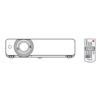
Do you have a question about the Panasonic PT-VX500U and is the answer not in the manual?
Covers elevation-based fan control settings and handling lead-free solder.
Critical safety parts require manufacturer-specified replacements to prevent hazards.
Includes FCC compliance, unauthorized modification warnings, and UV radiation precautions.
Guidelines for safe servicing, including unplugging power, isolation transformers, and lead dress.
Procedure to measure leakage current using a voltmeter to prevent electric shock.
Precautions when handling the lamp unit, including UV radiation and potential explosion risks.
Covers model, power, LCD panel, lens, lamp, light output, and signal frequency support.
Details terminal connections, cabinet, dimensions, weight, operating environment, and remote control.
Protects against overheating by cutting lamp power supply at high temperatures.
Safety switch that disables lamp operation if the cover is not properly secured.
Details the main fuse location, symptoms of a blown fuse, and replacement steps.
Automatic shutdown mechanism triggered by high temperature, fan failure, or power supply issues.
Guidance on cleaning the projector's exterior and projection lens surfaces.
Detailed steps for removing and installing the air filter units on the side and back.
Includes resetting the filter counter and attaching the lens cap for protection.
Procedure to display the projector's total lamp used time and cumulative operating time.
Details warning messages and function limitations when using non-standard lamps.
Procedures for cleaning with air spray or disassembly, focusing on optical parts.
Guidance on cleaning the projection lens and the projector cabinet exterior.
Descriptions of security functions: key lock, PIN code lock, and logo PIN code lock.
Procedure to reset key lock, PIN code lock, and logo PIN code lock to factory defaults.
Explains two standby modes (Eco and Network) and their impact on projector functions.
Table detailing which functions are restricted in Eco or Network standby modes.
Provides a flow chart outlining the sequence for mechanical disassembly and screw specifications.
Removing LCD panel/prism assembly and identifying its type.
Steps for removing lens, polarized glass, condenser lens, PBS, and integrator assemblies.
Removing the optical unit top and guidance on correct part placement and direction.
Tasks required after replacing the MAIN board: EEPROM, serial, and model number settings.
Setting color/gamma data and replacing EDID IC after MAIN board replacement.
Summary of optical adjustments (contrast, center) required after replacing parts.
Summary of electrical adjustments (fan, panel, auto-cal, common center, gamma, color, keystone).
Safety precautions including UV protection and time limits for optical adjustments.
Detailed steps for performing contrast adjustment using a slot screwdriver.
Steps to adjust optical center for white color uniformity using slot screwdriver.
Guide to service mode access, circuit adjustment warnings, and UV safety.
Steps for adjusting fan voltage, panel type, auto-calibration, common center, gamma, color, and keystone.
Location of test points on MAIN board and table of service adjustment parameters.
Overall chassis layout and system control circuit block diagram.
Block diagrams for lamp control, audio processing, power supply, and fan control systems.
Interpreting indicator lights and understanding general troubleshooting notes and remedies.
Diagnosing no power issues and checking the lamp cover switch (SW901).
Flowcharts and steps to diagnose and resolve no picture and no sound problems.
Explains the RS-232C connection and details pin assignments and signal names.
Defines communication conditions such as baud rate, character length, and sync method.
Explains the basic command format and the format with sub-commands for projector control.
Reference for control commands and cable specifications for computer connection.
Details signals and functions for scaler I/O ports like UART, GAMMA, EEPROM, and Keystone.
Block diagrams for major ICs including PF control, Sub CPU, RS-232C, GAMMA, S&H, Audio, Scaler, IRIS.
Block diagrams for SSC9512S (Power Switching) and PIC32MX695F512H (Network).
Block diagrams for TPS54286 (DC-DC converter) and STR-A6079 (Power switching).
Highlights critical safety parts requiring manufacturer-specified replacements.
Exploded views detailing components of the cabinet top and main/AV board assemblies.
Exploded views of cabinet bottom-1 and bottom-2 assemblies, detailing internal components.
Exploded views of various optical assemblies including lens, glass, integrator, condenser, and LCD panel.
Printed wiring board diagrams for AV, ID CONNECT, and RC (Sides A and B).
Diagrams of the MAIN PWB (Sides A and B), showing component layout and connector labels.
Diagrams of the AC 1st Filter PWB (Sides A and B), showing component layout.
Introduction to schematic diagrams, signal indications, and essential safety cautions.
Detailed schematic of the power supply, including AC input, switching, and protection circuits.
Schematics for AV, HDMI, PC signal processing, audio paths, and scaler connections.
Schematics for the main unit and specific input/output paths like HDMI, PC, and RC.

