1-13
1
S
HP
M
M
EC
P
ø9.52
(3/4")
S
HP
M
M
EC
P
ø12.7
(3/4")
1-5. Refrigerant Flow Diagram
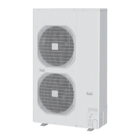
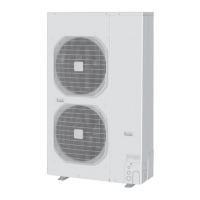
Outdoor Unit : U-200PE1E8
Outdoor Unit : U-250PE1E8
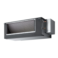
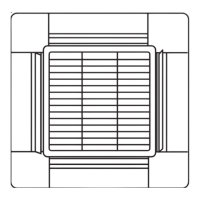
Indoor Unit : S-200PE1E8
Compressor
High pressure
switch
Heat
exchanger
Accumulator
Gas line
service valve
Check valve
4-way valve
Liquid line
service valve
Freeze-prevention coil
(Attached to the heat exchanger)
Strainer
Heat
exchanger
Strainer
Distributor
Heat
exchanger
Strainer
Distributor
Heat
exchanger
Distributor
Accumulator
Compressor
Accumulator
Gas line
service valve
4-way valve
Liquid line
service valve
Strainer
Freeze-prevention coil
(Attached to the heat exchanger)
Accumulator
Strainer
Cooling cycle
Heating cycle
Solenoid
valve
Solenoid
valve
Distributor
Liquid tank
Strainer
ø25.4 (brazing)
Solenoid
valve
High pressure
switch
Check valve
Solenoid
valve
ø25.4 (brazing)
Temperature
Cooling
Heating
Outdoor air intake temp.
43°C DB
–15°C DB
15°C WB
–20°C WB
Indoor air intake temp.
32°C DB / 23°C WB
18°C DB / 14°C WB
30°C DB / – WB
-
Minimum
Minimum
Maximum
Maximum
1-6. Operating Range
Indoor Unit : S-250PE1E8
SM830194-02BigPAC-i.indb13SM830194-02BigPAC-i.indb13 2012/09/0311:23:362012/09/0311:23:36
 Loading...