2
2-22
Outdoor unit control PCB
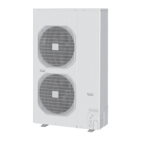
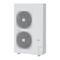
8 – 10 HP
2-22-2. Setting outdoor unit system addresses
For the basic wiring diagram (Set the system addresses: 1, 2, 3...)
ON
1
2
8 – 10 HP
Fig. 2-20
System address rotary switch
System address rotary switch
(Set to “0” at time of shipment)
System address
10s 20s
DIP switch
ON
OFF
System address
No.
System address 10s
digit
(2P DIP switch)
System address
1s place
(Rotary switch)
0 Automatic address
(Setting at shipment = “0”)
Both OFF
ON
ON
OFF
12
“0” setting
1 (If outdoor unit is No. 1)
Both OFF
ON
ON
12
“1” setting
2-22-3. Checking indoor unit addresses
Use the remote controller to check the addresses of the indoor
units. Press and hold the
button and button for 4
seconds or longer (simple settings mode, “ALL” appears on the
remote controller). Then press the
button and select the
indoor address.
(For the system addresses of the No. 1 outdoor unit, each time
the button is pressed, the address changes as follows: 1-1, 1-2, ...)
The indoor unit fan operates only at the selected indoor unit.
Confirm the indoor unit address.
Press the
button again to return to the normal remote
controller mode.
Fig. 2-21
LED1
FUSE (0.5A, F500)
OC (CN500, BLU)
MOV2
(CN301, BLK)
MOV1
(CN300, WHT)
EMG (CN502, BRN)
SILENT (CN037, WHT)
PUMP DOWN (CN048)
TEMINAL (CN205, BLK)
R.C.ADD. Rotary switch
C2 (CN020, WHT)
C1 (CN021, WHT)
TEST (CN033, RED)
TD (CN024, BLK)
TO (CN023, BLK)
TS (CN022, RED)
63PH (CN027, WHT)
EXCT
(CN030, RED)
RC P
(CN039, RED)
IC002
CTL2
(CN202, GRN)
CTL1
(CN203, GRN)
FUSE
(6.3A, F101)
N.P.CHECK
(CN046, RED)
LED2
MODE (CN038)
D115
(POWER LED)
IC001
R.C.ADD. DIP switch
A.ADD (CN047)
C-CHK (CN035)
EEPROM
LED (D041
EEPROM LED)
SM830194-00.indb22SM830194-00.indb22 2011/04/0619:12:502011/04/0619:12:50
 Loading...