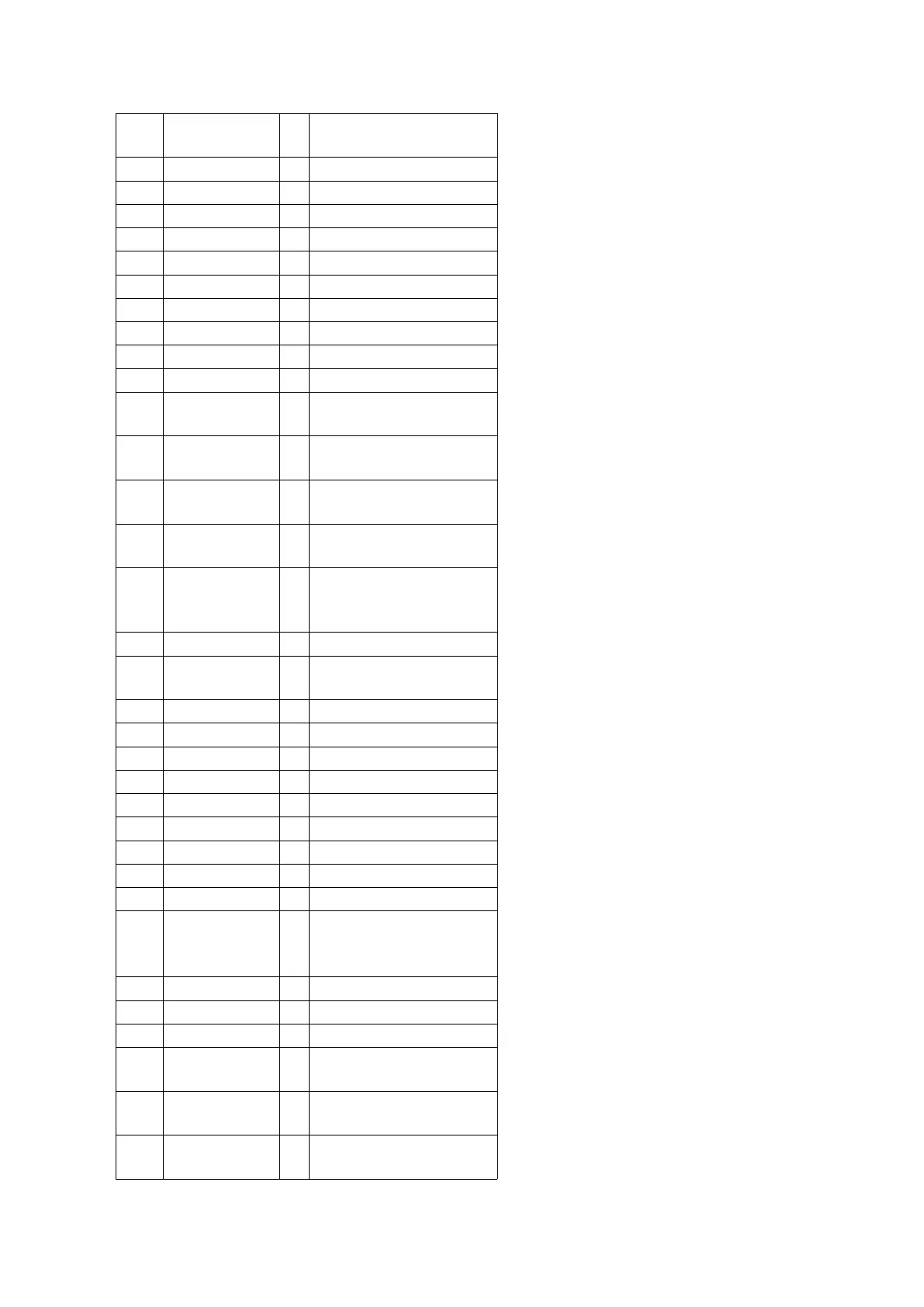
Pin
No.
Mark I/O Function
65 SW_LED O SUB WOOFER LED
66 VOL_LED O VOLUME_LED
67 V_JOG_A I Volume Jog A
68 V_JOG_B I Volume Jog B
69 FL_RESET O FL Driver reset
70 FL_CS I/O FL Driver Chip Select
71 FL_DOUT O Serial Data To FL Driver
72 FL_CLK I/O Serial Clock To FL Driver
73 H.BASS_LED O H.BASS LED
74 CD_RST O CD Reset Output
75 STATUS I CD Servo LSI Status
Input
76 MLD O CD Command Load
Output
77 MDATA O CD Command Data
Output
78 MCLK O CD Command Clock
Output
79 /RESTSW I CD Limit Switch Input
for the most Inner Point
(Active Low)
80 HOME_SW I Home Switch for CRS1
81 SPEED O SPEED is For CRS1
(cater)
82 CLOSE_SW I CLOSE SW is for CRS1
83 OPEN_SW I Open_Sw for CRS1
84 CHG_CW O CRS1 motor CW
85 CHG_CCW O CRS1 motor CCW
86 ST_SW I Stock_Sw for CRS1
87 PLAY_SW I Play_Sw for CRS1
88 CHG_PLR O Plunger for CRS1
89 BOTTOM_SW I Bottom_SW for CRS1
90 UP_SENSOR I UD-Sensor for CRS1
91 DECK2 I DECK CONDITION
INPUT 2
(R_INHF/MODE2/HALF2)
92 KEY3 I KEY3 INPUT
93 KEY2 I KEY2 INPUT
94 KEY1 I KEY1 INPUT
95 PHOTO_2 I Rotation Detection
Signal (Deck 2)
96 AVSS - Analog Power Supply
Input (Connect to GND)
97 PHOTO_1 I Rotation Detection
Signal (Deck 1)
79



 To Next Page