Do you have a question about the Panasonic SA-DK20 and is the answer not in the manual?
Details power output, THD, frequency response, and impedance for amplifier section.
Covers frequency range and sensitivity for the FM tuner.
Covers frequency range and sensitivity for the AM tuner.
Lists track system, heads, motor, recording system, and tape speed.
Details the procedure for performing insulation resistance tests for safety.
Precautions for grounding to prevent damage from static electricity.
Specific handling precautions for the traverse unit and optical pickup.
Overview of self-diagnosis functions and error conditions.
Procedures for entering and displaying self-diagnostic modes and codes.
Explanation of the tray lock functions (A and B).
Overview of pseudo ROM correction capabilities.
Explains how to interpret EEPROM flag indicators for status checks.
Describes how to display and interpret CHECK SUMs for system components.
Procedures for replacing major components like traverse deck and power amplifier.
Steps for disassembling and assembling the traverse unit.
Steps for disassembling and assembling the disc tray.
Procedures for checking the main and DVD F/E printed circuit boards.
Steps for disassembling the DVD/CD changer unit.
Procedures for checking major printed circuit boards.
Steps for disassembling the middle chassis assembly.
Steps for handling the terminal printed circuit board.
Steps for disassembling and removing the traverse gear.
Precautions for handling and replacing the optical pickup unit.
Measurement conditions and instruments for cassette deck adjustments.
Procedure for adjusting the head azimuth for optimal playback.
Steps for adjusting tape speed on the cassette deck.
Checks for bias and erase voltage settings on the cassette deck.
Details the pin functions of the system microprocessor IC601.
Exploded view and part numbers for the deck mechanism.
Exploded view of the CD loading mechanism and part locations.
Exploded view showing the location of cabinet parts.
| Brand | Panasonic |
|---|---|
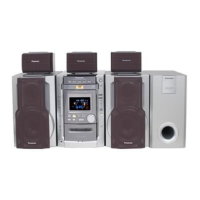
| Model | SA-DK20 |
| Category | Home Cinema speakers |
| Language | English |