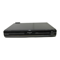
Do you have a question about the Panasonic SA-BTT405P and is the answer not in the manual?
Provides important safety notices and general precautions for servicing.
Details the procedure for performing a cold check for leakage current.
Describes the method for performing a hot check for leakage current.
Explains the protection circuitry and conditions for its operation.
Details methods to prevent damage from static electricity to sensitive components.
Provides cautions and safety guidelines regarding the laser diode.
Discusses essential measures to protect against static electricity.
Details grounding procedures to prevent electrostatic damage.
Provides specific instructions for grounding work tables.
Outlines procedures for grounding the human body.
Details precautions for exchanging the drive unit.
Provides technical information for authorized service personnel.
Explains the procedure for updating the unit's firmware.
Details the steps to check the current firmware version.
Describes methods available for updating firmware.
Details the process for updating firmware using an internet connection.
Details the procedure for updating firmware using a USB storage device.
Provides general specifications for the unit.
Details specifications related to the speaker system.
Lists specifications for the amplifier section.
Outlines specifications for the unit's various terminals.
Provides specifications for the Bluetooth functionality.
Details specifications for the FM tuner.
Lists specifications related to video output.
Lists various software licenses, trademarks, and copyrights.
Provides instructions for connecting the speaker cables.
Details how to connect the unit to a TV via HDMI.
Provides instructions for connecting the FM antenna.
Provides steps for forcibly ejecting a disc from the drive.
Offers an alternative method for disc ejection when normal operation fails.
Explains the multiple pressing function on the remote control.
Guides users on accessing special modes via remote control button combinations.
Details the procedure for entering and using Open Mode with specific remote buttons.
Details entering and using Privately Mode 1 via remote control.
Details entering and using Privately Mode 2 via remote control.
Provides an introduction to the service mode and its purpose.
Outlines the step-by-step procedure to access the service mode.
Provides instructions on how to properly exit the service mode.
Lists the available commands and their functions within service mode.
Details the self-diagnosis functions for identifying errors.
Provides general troubleshooting steps for set operation issues.
Outlines the procedures to follow after completing service tasks.
Presents a flowchart detailing the unit disassembly procedure.
Illustrates the physical locations of the various PCBs within the unit.
Details the procedure for removing the top panel of the unit.
Provides instructions for removing the front panel unit.
Details the procedure for removing the tray ornament.
Outlines the steps to remove the front and NFC PCB units.
Details the procedure for removing the body chassis.
Provides instructions for removing the power supply PCB unit.
Details the procedure for removing the fan motor unit.
Provides instructions for removing the digital PCB unit.
Details the procedure for removing the mechanism unit.
Provides instructions for removing the AC inlet unit.
Covers drive adjustment procedures after replacing specific unit components.
Lists specific tools required for PC method adjustments.
Lists commercial tools necessary for both adjustment methods.
Outlines the necessary preparation steps before starting adjustments.
Details the step-by-step process for performing adjustments using a PC.
Details the step-by-step process for performing adjustments using the remote control.
Lists service tools required for replacing front or NFC PCB units.
Lists the commercial tools necessary for PCB replacement procedures.
Provides instructions for installing the tag writer software.
Guides on writing the Bluetooth MAC address to the NFC module.
Lists standard inspection criteria to ensure proper operation post-repair.
Provides a detailed list of replaceable parts with their part numbers.
Presents an exploded view of the casing and mechanism components.
Details the packing procedures and included accessories.
| Brand | Panasonic |
|---|---|
| Model | SA-BTT405P |
| Category | Home Cinema speakers |
| Language | English |



 Loading...