EasyManua.ls Logo

Panasonic SA-PT150GCP - User Manual

Panasonic SA-PT150GCP
107 pages
Print Icon
To Next Page IconTo Next Page
Loading...
lGENERAL
Power Supply: AC 110 to 240 V, 50/60 Hz
Power Consumption: Main unit 105 W
Power Consumption in Standby Mode:
approx. 1 W
Dimensions (W×H×D):
430×60×342 mm
Mass: Main unit 3 kg
Operating Temperature Range: +5°C to +35°C
Operating Humidity Range: 5% to 90% RH (no
condensation)
lAMPLIFIER SECTION
RMS Output Power: Dolby Digital Mode
lTotal RMS Dolby Digital mode power:
330 W
At 1 kHz and total harmonic of 10%
lFront Ch: 55 W / Channel (5 )
lCenter Ch: 55 W / Channel (5 )
lSurround Ch: 55 W / Channel (5 )
At 100 Hz and total harmonic of 10%
lSubwoofer Ch: 55 W / Channel (5 )
PMPO Output Power: 2800 W
DIN Output Power: Dolby Digital Mode:
lTotal DIN Dolby Digital mode power:
150 W
At 1 kHz and total harmonic of 1%
© 2007 Matsushita Electric Industrial Co., Ltd. All
rights reserved. Unauthorized copying and
distribution is a violation of law.
SA-PT150GC
SA-PT150GCP
SA-PT150GCS
SA-PT150GCT
SA-PT150GS
Colour
(S).......................Silver Type
lFront Ch: 25 W / Channel (5 )
lCenter Ch: 25 W / Channel (5 )
lSurround Ch: 25 W / Channel (5 )
At 100 Hz and total harmonic of 1%
lSubwoofer Ch: 25 W / Channel (5 )
lFM TUNER, TERMINALS SECTION
Preset Memory: FM 30 stations
Frequency Modulation (FM)
Frequency range: 87.50-108.00 MHz
(50-kHz step)
Sensitivity: 1.8 µV (IHF)
S/N 26 dB: 1.4 µV
Antenna terminals: 75 (unbalanced)
Mic Jack:
Sensitivity:
0.7 mV (1.2 k)
Terminal: Mono, 6.3 mm jack (1 system)
lUSB SECTION
USB Port:
USB standard: USB 2.0 full speed
Media file format support: MP3 (*.mp3)
WMA (*.wma)
JPEG (*.Jpg, *.JPEG)
MPEG4 (*.asf)
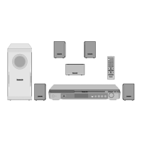
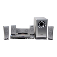
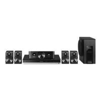
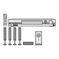
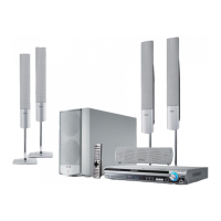
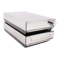
DVD Home Theater Sound System
Specifications
ORDER NO. MD0705010CE

Table of Contents

Questions and Answers

  • E
    Erik JacksonAug 15, 2025
    Why is there no power supply to my Panasonic SA-PT150GCP?
    • A
      April MartinezAug 16, 2025
      If your Panasonic Home Cinema speakers have no power, verify the AC cord connection for any opens or shorts. Inspect the fuse F1 on the SMPS Module P.C.B. Check the supply voltage to the Main P.C.B. from the SMPS Module P.C.B. (+5V/+7V/2.7V). Ensure the cable connection between the SMPS Module & Main P.C.B. is secure. Check the DC voltage (+9.1V).
  • C
    Christopher AndersonAug 18, 2025
    What to do if my Panasonic Home Cinema speakers have no audio output?
    • J
      Johnny AndersonAug 18, 2025
      If there's no audio output from your Panasonic Home Cinema speakers, first check the speaker connections and solderability. Then, check the amplifier IC circuit (audio output) and the power supply to the amplifier IC.
  • Z
    Zachary HarmonAug 21, 2025
    What to do if my Panasonic Home Cinema speakers cannot read CD/DVD disc but spindle motor is spinning?
    • C
      Christopher BarnesAug 21, 2025
      If your Panasonic Home Cinema speakers cannot read a CD/DVD disc, but the spindle motor is spinning, check the laser drive circuitry for voltages and current. Specifically, check the CD Laser Drive and DVD Laser Drive, comparing voltages and LD current with a known good DVD Module P.C.B.
  • B
    Brandon ThompsonAug 25, 2025
    What to do if my Panasonic SA-PT150GCP Home Cinema speakers cannot read data from USB?
    • W
      William NolanAug 26, 2025
      If your Panasonic Home Cinema speakers cannot read data from USB, check the USB connector & FFC. Also, check the LSI O/P and the IC supply (+5V).
  • V
    vanessamarshallAug 27, 2025
    What to do if the Panasonic Home Cinema speakers have No FL Display?
    • P
      Paul PattersonAug 27, 2025
      If the Panasonic Home Cinema speakers display is not working, check the supply voltage, referring to Item 1 checking points. Also, check SYS6V to IC2018, the oscillator circuit, and the soldering condition.
  • V
    Veronica SmithAug 30, 2025
    Why is there block noise during play on my Panasonic Home Cinema speakers?
    • A
      Alison WeeksAug 31, 2025
      If you are experiencing block noise during playback on your Panasonic Home Cinema speakers, check the SDRAM address and data bus signal.
  • T
    Terry MooreSep 2, 2025
    Why is there Jitter out of specification on my Panasonic SA-PT150GCP Home Cinema speakers?
    • B
      Brenda HuffSep 3, 2025
      If the jitter is out of specification on your Panasonic Home Cinema speakers, check the LD current and the OPU (consider changing to another unit to confirm the operating condition).
  • K
    Kristin EricksonSep 6, 2025
    What to do if disc not spinning on my Panasonic Home Cinema speakers?
    • V
      Vincent TrujilloSep 6, 2025
      If the disc isn't spinning, the traverse isn't moving, or there's abnormal movement with the traverse and spindle on your Panasonic Home Cinema speakers, check the connection from the DVD Module to the Traverse unit. Also, check the motor driver circuitry for voltages and control signals, comparing with a known good DVD Module P.C.B.
  • M
    mfowlerSep 9, 2025
    Why is there no TOC / Long TOC on my Panasonic SA-PT150GCP Home Cinema speakers?
    • L
      lesliegravesSep 9, 2025
      If your Panasonic Home Cinema speakers are showing 'No TOC' or 'Long TOC', check the motor driver circuitry (+5V). Also, check the laser drive circuitry (Voltages & current), and the LSI IC connection to motor drive circuitry. Compare these with a known good DVD Module P.C.B.
  • G
    Gloria WrightSep 12, 2025
    How to troubleshoot distorted picture or abnormal sound during initialization of Panasonic Home Cinema speakers?
    • A
      adriana18Sep 12, 2025
      If you experience a distorted picture or abnormal sound during the initialization of your Panasonic Home Cinema speakers, check the SDRAM address, data bus, CLK, and other control signals waveform. Also, check the video signals and the audio DAC circuitry, comparing these with a known good DVD module P.C.B.

Summary

1 Safety Precautions

1.1 General Guidelines

General safety guidelines for servicing, including lead dress and insulation checks.

1.2 Before Repair and Adjustment (Using SMPS Module P.C.B.)

Cautions for working with the SMPS module and initial power-up procedures.

1.5 Caution for AC Cord

Safety precautions for handling the AC cord and plug, especially for specific regions.

2 Prevention of Electro Static Discharge (ESD) to Electrostatically Sensitive (ES) Devices

3 Precaution of Laser Diode

5 Handling Precautions for Traverse Unit

5.1 Cautions to Be Taken in Handling the Optical Pickup Unit

Specific warnings about handling the optical pickup to prevent ESD damage.

5.2 Grounding for electrostatic breakdown prevention

Procedures for grounding worktables and human bodies to prevent ESD.

8 Self-Diagnosis and Special Mode Setting

8.1 Service Mode Summary Table

A summary table listing service modes, player buttons, and applications.

8.2 Service Mode Table

Detailed explanations of various service modes for checking unit functions.

8.2.1 Service Mode Table 1

Details of Service Mode Table 1, including jitter and error code checks.

8.2.2 Service Mode Table 2

Details of Service Mode Table 2, covering laser drive current measurements.

8.2.3 Service Mode Table 3

Details of Service Mode Table 3, for firmware and region display checks.

9 Assembling and Disassembling

10 Assembly and Disassembly of DVD Mechanism Unit

12 Measurements and Adjustments

12.1 Service Tools and Equipment

Lists the necessary tools and equipment for service and measurement tasks.

12.2 Important points in adjustment

Key considerations before performing optical and electrical adjustments.

12.4 Optical adjustment

Detailed steps for performing optical adjustments, including tilt and tangential.

14 Voltage and Waveform Chart

14.1. DVD Module P.C.B.

Voltage and waveform data specifically for the DVD Module PCB.

14.2. Main P.C.B.

Voltage and waveform data for test points on the Main PCB.

14.5. Waveform Chart

Visual representations of waveforms for various test points and ICs.

16 Wiring Connection Diagram

17 Block Diagram

17.1. System Control

Block diagram showing the system control circuitry and its connections.

17.2. DVD (Servo)

Block diagram illustrating the DVD servo system and its components.

17.6. Amp & Power

Block diagram illustrating the amplifier stages and power supply distribution.

19 Schematic Diagram

19.1. DVD Module Circuit

Schematic diagram for the DVD module, showing its electronic components and connections.

19.2. Main Circuit

Schematic diagram of the main circuit board, including audio and control sections.

20 Printed Circuit Board

21 Basic Troubleshooting Guide

21.1. Basic Troubleshooting Guide for Traverse Unit (DVD Module P.C.B)

Troubleshooting steps for issues related to the traverse unit and DVD module.

21.2. Basic Troubleshooting Guide for SMPS;MAIN;PANEL

Troubleshooting steps for power supply, main, and panel circuit problems.

22 Overall Block Diagram for PT150

22.1. SC-PT150 Simplified Block

A simplified block diagram illustrating the main functional blocks of the SC-PT150 unit.

23 Terminal Function of ICs

23.1. IC2018 (C2 CBYY000438): System Control IC

Pin terminal functions for the System Control IC (IC2018).

25 Replacement Parts List

25.1. Component Parts List

Detailed list of components, including part numbers, names, and remarks.

Panasonic SA-PT150GCP Specifications

General IconGeneral
BrandPanasonic
ModelSA-PT150GCP
CategoryHome Cinema speakers
LanguageEnglish

Related product manuals