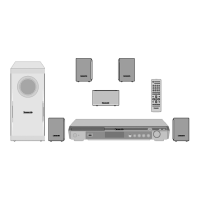
Step 2 Remove 1 screw from the regulator IC (IC2903).
Step 3 Remove the regulator IC (IC2903) from the heatsink
extrusion.
Caution : Handle the heatsink extrusion with caution due to its
high prolonged use. Touching it may lead to injuries.
Note : Refer to the diagrams of Main P.C.B. (Item 9.14.) for the
location of the part.
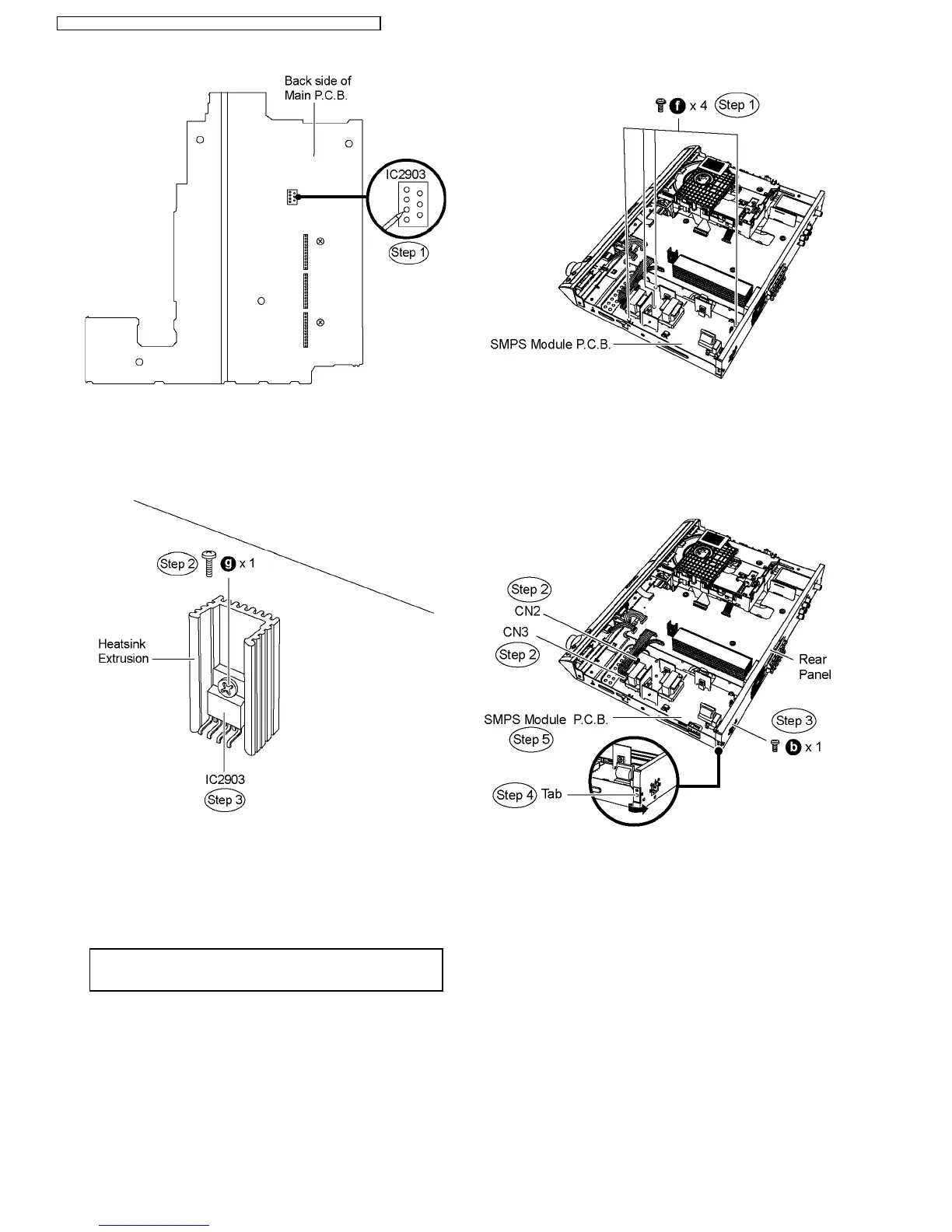
9.17. Disassembly of SMPS Module
P.C.B.
·
Follow (Step 1) to (Step 3) of Item 9.3.
Caution Note: The SMPS Module P.C.B. is advisable to be
replaced as a unit. Do not attempt to replace any individual
components on board.
Step 1 Remove 4 screws from SMPS Module P.C.B.
Step 2 Detach FFC cable from the connectors (CN2 & CN3) on
SMPS Module P.C.B.
Step 3 Remove 1 screw from the rear panel.
Step 4 Release tab of the rear panel in the direction of arrow.
Step 5 Remove SMPS Module P.C.B.
44
SA-PT150GC / SA-PT150GCP / SA-PT150GCS / SA-PT150GCT / SA-PT150GS
 Loading...