Operating humidity range 5% to 90% RH (no condensation)
n SPEAKER SECTION
Type 1 Way, 1 speaker system
Speaker(s) 8 cm (5 1/2”) cone type 6 Ω
Impedance 6 Ω
Input power 6 (MAX)
1 Safety Precautions
4
1.1. General Guidelines
4
1.2. Caution for fuse replacement
5
1.3. Before repair and adjustment
5
1.4. Protection Circuitry
5
1.5. Safety Parts Information
5
2 Prevention of Electro Static Discharge (ESD) to
Electrostatically Sensitive (ES) Devices
6
3 Precaution of laser diode
7
4 Handling Precautions For Traverse Unit
7
5 About Lead Free Solder (PbF)
9
5.1. Service caution based on legal restrictions
9
6 Accessories
10
7 Operation Procedures
11
7.1. Remote Control Key Buttons Operations
11
7.2. Main Unit Key Buttons Operations
11
7.3. Connection
12
7.4. Using the XMョ Satellite Radio
13
8 Self diagnosis and special mode setting
14
8.1. Service Mode Summary Table
14
8.2. Service Mode Table 1
14
8.3. Error Code Table 1
17
9 Assembling and Disassembling
19
9.1. Caution
19
9.2. Disassembly flow chart
20
9.3. Main Components & P.C.B. Locations
21
9.4. Disassembly of Rear Cabinet
22
9.5. Disassembly of XM Module P.C.B.
22
9.6. Disassembly of Panel P.C.B. & LED P.C.B.
22
9.7. Disassembly of Main P.C.B., Sensor P.C.B. & Tuner
P.C.B.
23
9.8. Disassembly of Switch P.C.B. & Traverse Unit
23
9.9. Disassembly of Power Switch P.C.B. & Tact Switch P.C.B.
24
9.10. Replacement of Traverse Cover
24
9.11. Disassembly of CD Servo P.C.B.
25
9.12. Disassembly of Motor Unit & Motor P.C.B.
26
Dimension (W x H x D) 121 mm x 236 mm x 146 mm
(4 3/4” x 9 9/32” x 5 3/4”)
Power consumption in standby mode:
2.0 W (appx.)
Notes:
·
Specifications are subject to change without notice.
·
Mass and dimensions are approximate.
9.13. Disassembly of CD Block & CD Lid
27
9.14. Disassembly of Speakers
28
10 Service Fixture and Tools
31
11 Service Positions
31
11.1. Check and Repair of CD Servo P.C.B.
32
11.2. Check and repair of Main P.C.B., Sensor P.C.B., Tuner
P.C.B., Motor P.C.B., Panel P.C.B., LED P.C.B., Power
Switch P.C.B., Tact Switch P.C.B., XM Module P.C.B. &
Switch P.C.B.
33
12 Voltage and Waveform Chart
34
12.1. Main P.C.B.
34
12.2. CD Servo P.C.B.
35
12.3. Motor P.C.B.
35
12.4. Panel P.C.B.
35
12.5. Tuner P.C.B.
35
12.6. Waveform Chart
36
13 Wiring Connection Diagram
37
14 Block Diagram
39
14.1. CD Servo
39
14.2. XM Module & Tuner
40
14.3. Main (1/2), Transformer, & Sensor
41
14.4. Main (2/2), Panel, LED, Power Switch, Tact Switch, Switch
& Motor
42
15 Notes of Schematic Diagrams
43
16 Schematic Diagram
45
16.1. (A) CD Servo Circuit
46
16.2. (B) XM Module Circuit
47
16.3. (C) Tuner Circuit
48
16.4. (D) Main Circuit
49
16.5. (E) Panel Circuit, (F) LED Circuit, (G) Power Switch
Circuit, (H) Tact Switch Circuit & (I) Switch Circuit
52
16.6. (J) Motor Circuit, (K) Sensor Circuit & (L) Transformer
Circuit
53
17 Printed Circuit Board
55
17.1. (A) CD Servo P.C.B., (B) XM Module P.C.B. & (C) Tuner
P.C.B.
56
17.2. (D) Main P.C.B.
57
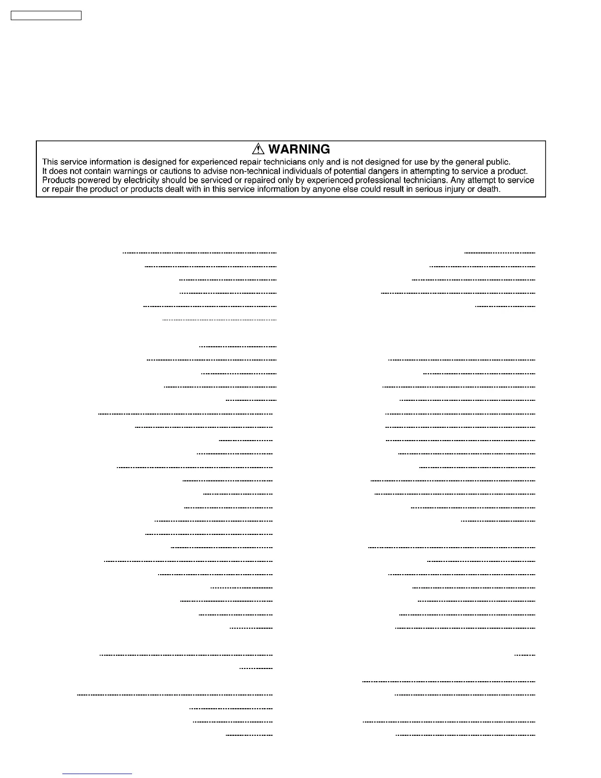
CONTENTS
Page Page
2
SC-EN35P / SC-EN35PC