15
7 Troubleshooting Guide
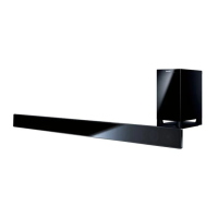
7.1 Main Unit (SU-HTB690)
7.1.1 No power
7.1.2. No Display on display panel
7.1.3. Bluetooth® Pairing failure
Touch the Power
No Dis
la
on
Caution:
Disconnect the AC cord
OK
turn on the unit.
display panel.
0Ω
at output side of Fuse.
[Refer to check point ①-①’]
= Check Rectifier Diode =
300 V and over output
at pin1 of Rectifier Diode .
[Refer to check point ②]
= Check Power Transformer and
Power Diode =
Over 21V and over output at 28V”.
[Refer to check point ③]
OK
OK
o
Change
Power PCB
Change
Power PCB
Change
Power PCB
No No
Confirm the voltage
at Pin1 of connector
XP113
when touch the
Less than 0.9V
In case of change the Main PCB, should
change the NFC PCB accordingly
No Display on display panel
unit.
3.3V and over Change Touch PCB
Touch the Power
button on the unit to
turn on the unit.
Press [ ] button on the
remote control.
Pairing and input
audio signal to
[Bluetooth].
Sound can be heard.
OK
No
24V At “VFD_24V”
[Refer to check point④]
No
OK
Change FL PCB
Still No Display
Change
Main PCB
Change
Main PCB
Change
Main PCB
on
Caution:
Disconnect the AC cord
0Ω
at output side of Fuse.
[Refer to check point ①-①’]
= Check Rectifier Diode =
300 V and over output
at pin1 of Rectifier Diode .
[Refer to check point ②]
= Check Power Transformer and
Power Diode =
Over 21V and over output at 28V”.
[Refer to check point ③]
OK
OK
o
Change
Power PCB
Change
Power PCB
Change
Power PCB
No No
Confirm the voltage
at Pin1 of connector
XP113
when touch the
Less than 0.9V
In case of change the Main PCB, should
change the NFC PCB accordingly
No Display on display panel
unit.
3.3V and over Change Touch PCB
Touch the Power
button on the unit to
turn on the unit.
Press [ ] button on the
remote control.
Pairing and input
audio signal to
[Bluetooth].
Sound can be heard.
OK
No
24V At “VFD_24V”
[Refer to check point④]
No
OK
Change FL PCB
Still No Display
Change
Main PCB
Change
Main PCB
Change
Main PCB
Touch the Power
button on the unit to
Press [ ] to
select
“
”
“SC-HTB690” is displayed on
the Bluetooth® device’s
“PAIRING” displays
Bluetooth® Pairing failure
Press and hold
[ - PAIRING]
OK
OK
OK
.
.
.
Go to
“No Key Function”
.
.
No
No
No
Change
Main PCB
Change
Main PCB
Connection of
Bluetooth® device
(“CONNECTED” displayed)
Sound output
No problem found
OK
OK
Change
Main PCB
No
Go to
“No Sound (Bluetooth®)”
No
AllPlay connect failure
Touch the Power
button to turn on the
unit
check 3.3V at
“AP3.3V_D”
[Refer to check
point ⑤ ]
check the FFC cable is
connect correct (Main
XP14 to ALLPlay J23
and Optical XP2 to
OK
No
Change
ALLPlay PCB or
Optical PCB
NG
Change
Main PCB
connect correct
or change
 Loading...
