9 © Panasonic Industrial Devices SUNX Co., Ltd. 2016
Connecting / Setting Procedures
2-3-2
When Using in Combination with Application Expansion Unit SF-C14EX
<The 8-core cable is used>
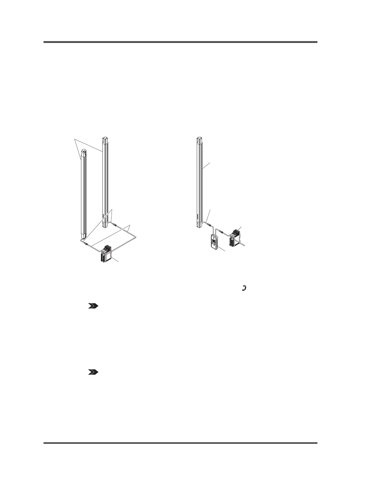
1. Set the SF4B / SF4B<V2> series and
SF-C14EX, and check that the SF4B /
SF4B<V2> series works properly. For
mounting method of SF4B / SF4B<V2>
series or SF-C14EX, refer to the respective
Instruction Manuals.
2. Turn OFF the power, and disconnect the ex-
tension cable with connectors connected to
the emitter side (or receiver side) of SF4B
/ SF4B<V2> series from SF-C14EX, and
then connect the emitter side (or receiver
side) of this device to the receiver side (or
emitter side) connector of SF-C14EX.
FUNCTION
㧙
CAN
C
EL
EN
TER
㧗
Bottom cap
cable
SF4B / SF4B<V2> series
(Emitter or receiver)
SF-C14EX
SF4B / SF4B<V2> series
(Receiver or emitter)
This device
3. Turn ON the power, and set the function with this device.
After the power of this device is ON, a total approx. 30 sec. will be taken for data transmission with
SF4B / SF4B<V2> series and SF-C14EX. While data transmission, “
” lights up in revolving.
[The safety output 1 / 2 of SF-C14EX series are set to “OFF” while this device has been connected.]
REFERENCE Refer to “3-2 Functional Descriptions <When Using in Combination with Application
Expansion Unit SF-C14EX>” for the details of the functions, and refer to “3-3 Function
Setting (Operation Procedure)” for the setting procedures of the functions respectively.
4. Turn OFF the power, and remove this device.
5. Connect the SF4B / SF4B<V2> series and SF-C14EX, and return the device to the state de-
scribed in procedure 1.
6. Check that the SF4B / SF4B<V2> series works as set at the procedure 3.
Then, inspect the SF4B / SF4B<V2> series.
REFERENCE Refer to “Chapter 4 Maintenance” of the SF4B / SF4B<V2> series instruction manual for
the details of the inspection of the SF4B / SF4B<V2> series.
Bottom cap
cable
SF4B / SF4B<V2>
series
Extension cable
with connectors
SF-C14EX
Ramco Innovations
800
280-6933 www.PanasonicSensors.com

 Loading...


