10© Panasonic Industrial Devices SUNX Co., Ltd. 2016
Connecting / Setting Procedures
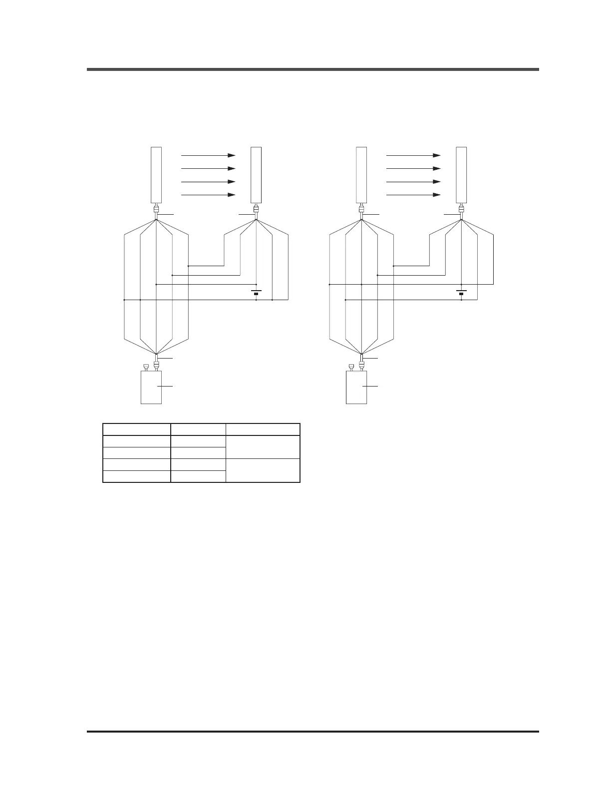
<In case this device cannot be connected between SF4B / SF4B<V2> series and the connecting cable>
Ɣ This device can be connected to SF4B / SF4B<V2> series by using the connection cable
with a connector on one end (optional).
<For PNP output> <For NPN output>
Ɣ Connection cable with a connector on one end: 2 pcs./set
Model No. Cable length Description
SFB-CC3 3m
For 8-core cable
SFB-CC10 10m
SFB-CC3-MU 3m
For 12-core cable
SFB-CC10-MU 10m
The setting procedure remains the same.
The control output (OSSD 1 / 2) of SF4B / SF4B<V2> series is set to “OFF” while this de-
vice has been connected. (The safety output 1 / 2 of SF-C14EX is also set to “OFF” while
SF-C14EX has been used.) Once the setting is completed, turn OFF the power, remove this de-
vice and then turn ON the power again.
Connecting cable
with a connector
on one end
24V±10%
+
-
Connecting cable with a
connector on one end
This device
Emitter
Receiver
(Shield)
(Blue)
(Brown)
(Orange)
(Orange
/ Black)
(Shield)
(Blue)
(Brown)
(Orange)
(Orange
/ Black)
(Shield)
(Blue)
(Brown)
(Orange)
(Orange / Black)
Connecting cable
with a connector
on one end
24V±10%
+
-
Connecting cable with a
connector on one end
This device
Emitter
Receiver
(Shield)
(Blue)
(Brown)
(Orange)
(Orange
/ Black)
(Shield)
(Blue)
(Brown)
(Orange)
(Orange
/ Black)
(Shield)
(Blue)
(Brown)
(Orange)
(Orange / Black)
Ramco Innovations
800
280-6933 www.PanasonicSensors.com

 Loading...


