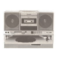
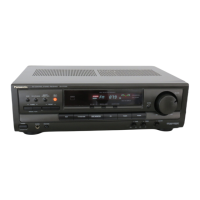
The provided document is a service manual for the National Panasonic Compact Stereo Receiver SG-250R/25Q. This device is a multi-band stereo receiver, integrating an amplifier section with FM, LW, MW, and SW tuner capabilities. It is designed to provide audio amplification and radio reception across various frequency bands, making it a versatile component for a home audio system.
Function Description
The SG-250R/25Q serves as the central control unit for a compact stereo system, offering both radio reception and signal amplification for external audio sources. Its primary functions include:
- Radio Reception: It can tune into multiple radio bands:
- FM (Frequency Modulation): For high-fidelity stereo broadcasts.
- LW (Long Wave): Primarily used for broadcasting in Europe, parts of Asia, and Africa.
- MW (Medium Wave): Also known as AM (Amplitude Modulation), common for local and regional broadcasts.
- SW (Short Wave): Used for long-distance international broadcasting and amateur radio.
- Audio Amplification: The built-in amplifier boosts audio signals from the tuner or connected external devices (Phono, Aux, Tape) to drive loudspeakers.
- Input Selection: Allows users to switch between different audio sources, such as the built-in tuner, a turntable (Phono), or other auxiliary devices (Aux, Tape).
- Tone Control: Provides basic audio adjustments for bass and treble to tailor the sound output to user preference or room acoustics.
- High Filter: A feature to reduce high-frequency noise, often useful when listening to older recordings or broadcasts with static.
- Recording Output: Offers a dedicated output for connecting a tape recorder, allowing users to record radio programs or other audio sources.
Important Technical Specifications
The manual details comprehensive specifications for both the amplifier and tuner sections:
Amplifier Section:
- Power Output:
- MPO (Music Power Output): 2 x 32 W (THD 1%, 4 ohms)
- RMS (Root Mean Square) (One Channel Driven): 2 x 27 W (THD 1%, 4 ohms)
- RMS (Both Channels Driven): 2 x 22 W (THD 1%, 4 ohms)
- Frequency Response: 10 Hz ~ 25 kHz, ±1.5 dB (DIN), indicating a wide and relatively flat frequency reproduction.
- Input Sensitivity and Impedance:
- Phono: 2 mV, 47k ohms (suitable for magnetic cartridges)
- Aux: 300 mV, 100k ohms
- Tape: 300 mV, 30k ohms
- Rec. Out and Impedance (DIN): 30 mV, 82k ohms
- Tone Controls:
- Bass: ±10 dB at 50 Hz
- Treble: ±10 dB ~ ±16 dB at 10 kHz
- High Filter: -6 dB/oct. from 7 kHz
FM Tuner Section:
- Frequency Range: 87.5 MHz ~ 108 MHz (standard FM broadcast band).
- Intermediate Frequency: 10.7 MHz
- Sensitivity:
- 2.5 µV (IHF)
- 3.5 µV (S/N 26 dB, MOD 40 kHz) (DIN)
- Image Ratio: 45 dB (98 MHz)
- Signal to Noise Ratio: 60 dB (at 1 kHz, 60 dB, 40 kHz) (Unweighted) (DIN)
- Distortion:
- Mono: 0.6% (at 1 kHz, 60 dB, 100%)
- Stereo: 0.8% (at 1 kHz, 60 dB, 100%)
- Stereo Separation:
- 35 dB (at 1 kHz, 60 dB, 30%)
- ≥ 30 dB, 250 Hz ~ 6.3 kHz (60 dB, 30%) (DIN)
- ≥ 18 dB, 6.3 kHz ~ 12.5 kHz (60 dB, 30%) (DIN)
AM Tuner Section (includes MW, LW, SW):
- Frequency Range:
- MW: 525 kHz ~ 1,605 kHz (572 m ~ 187 m)
- LW: 145 kHz ~ 285 kHz (2,070 m ~ 1,050 m)
- SW: 5.9 MHz ~ 18 MHz (50.8 m ~ 16.7 m)
- Intermediate Frequency: 455 kHz (except UK: 470 kHz)
- Sensitivity:
- MW: 100 µV/m for 50 mW (1 MHz)
- LW: 250 µV/m for 50 mW (220 kHz)
- SW: 8 µV for 50 mW (12 MHz)
- Image Ratio:
- MW: 45 dB (1 MHz)
- LW: 43 dB (220 kHz)
- SW: 15 dB (12 MHz)
General Specifications:
- Power Consumption: 155 W
- Power Supply: AC 100 V, 120 V, 220 V, 240 V, 50/60 Hz (multi-voltage compatibility).
- Dimensions (W×H×D) (Center Unit): 552 mm x 105 mm x 306 mm (21-25/32" × 4-1/8" × 12-3/64")
- Weight (Center Unit): 7.4 kg (16 lb. 5 oz.)
Usage Features
The SG-250R/25Q is designed for straightforward operation within a home audio setup.
- Multi-Band Radio: The inclusion of FM, LW, MW, and SW bands provides extensive radio listening options, from local stereo broadcasts to international shortwave transmissions.
- Multiple Audio Inputs: With Phono, Aux, and Tape inputs, users can connect a variety of external audio sources, such as turntables, CD players, cassette decks, or other media devices, making it a versatile hub for a compact stereo system.
- Recording Capability: The Tape Rec. Out allows for easy connection to a recording device, enabling users to capture audio from any selected source.
- User Controls: Front panel controls for input selection, tuning, volume, balance, bass, treble, and high filter provide comprehensive command over the audio experience.
- Dial Cord Stringing Guide: The manual includes a detailed diagram for the dial cord stringing, which is crucial for the proper functioning of the analog tuning mechanism. This guide is a key feature for maintenance and repair, ensuring accurate frequency selection.
Maintenance Features
The service manual is primarily focused on enabling technicians to maintain and repair the device. Key maintenance features include:
- Disassembly Instructions: Step-by-step guidance on how to remove components like knobs, rear board mounting screws, and the cabinet from the chassis. This is essential for accessing internal parts for repair or replacement.
- Location of Parts Diagram: A detailed exploded view diagram (FIG. 3) showing the physical placement of various components and screws within the chassis. This aids in identifying and locating specific parts during disassembly and reassembly.
- Alignment Instructions (Radio): Comprehensive procedures for aligning the AM and FM tuner sections, including specific test points (TP101, TP201, TP202) and adjustments for IFTs, OSC coils, and ANT coils across all bands. This ensures optimal reception and performance of the radio.
- Dummy Antenna Diagrams: Instructions and diagrams for constructing dummy antennas (FIG. 8) are provided, which are necessary for accurate alignment procedures.
- Schematic Diagram: A full schematic diagram (FIG. 6) illustrates the electrical connections and components of the amplifier and tuner circuits. This is invaluable for troubleshooting electrical faults and understanding the circuit design.
- Wiring Diagram: A detailed wiring diagram (FIG. 7) shows the interconnections between different circuit boards and components, including power supply, switches, and input/output jacks. This helps in tracing signal paths and identifying wiring issues.
- Replacement Parts List: Extensive lists of replacement parts, categorized by resistors, capacitors, switches, chassis components, cabinet parts, and packing materials. Each entry includes the reference number, part number, description, and quantity, facilitating the ordering of correct replacement components.
- Part Rank System: A ranking system (A, B, C) is used for parts, indicating their importance for repair and availability. "A" rank parts are critical and will be stocked for a longer period.
- Safety Parts: Specific parts are marked with "SAFETY" in the remarks column, indicating that they are critical for safety and should only be replaced with identical parts to maintain the safety standards of the device.
In summary, the National Panasonic SG-250R/25Q is a robust compact stereo receiver offering multi-band radio reception and audio amplification. Its detailed service manual provides all necessary information for technicians to perform comprehensive maintenance, troubleshooting, and repair, ensuring the longevity and optimal performance of the device.