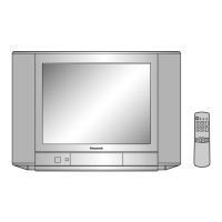
This document provides a comprehensive overview of a remote control unit, specifically the EUR501310 model, and its integration within a larger electronic system, likely a television or similar display device. The information spans from the remote control's internal circuitry and key functions to the detailed schematics of the main device, including power supply, signal processing, and display components.
Remote Control Unit (EUR501310)
Function Description:
The EUR501310 is a dedicated remote control unit designed to interface with a compatible electronic device, enabling user interaction through a series of predefined key presses. It operates by generating specific data codes corresponding to each key, which are then transmitted wirelessly (likely via infrared, given the typical design of such units) to the main device for command execution. The core of the remote control is an integrated circuit (IC) labeled EFOEC3524K4W, which handles key scanning, code generation, and signal modulation.
Important Technical Specifications:
- Power Supply: The remote control operates on a 3V supply, likely provided by two 1.5V batteries.
- Oscillator: An internal oscillator (implied by the presence of C1, C2, R1, and R2, typically forming an RC oscillator or crystal oscillator circuit) is used for timing and signal generation.
- Output Signal: The modulated signal is output via TP1, likely an infrared LED driver circuit.
- Key Matrix: The remote control features a key matrix connected to the IC, with inputs for Xout (pins 20, 19) and Xin (pins 5, 4), and data output lines (D0-D7) from pins 18-11.
- Key Codes: A detailed table maps 22 distinct key numbers to their respective functions and corresponding data codes (ON and OFF values). These codes are crucial for the main device to interpret commands.
Usage Features:
The remote control offers a wide range of functions, categorized as follows:
- Basic TV/Video Control: TV/VIDEO (Key 1), TV POWER (Key 22).
- Channel Navigation: CH 1-9 (Keys 5-13), CH 0 (Key 14), CH UP (Key 18), CH DOWN (Key 19).
- Volume Control: VOLUME UP (Key 15), VOLUME DOWN (Key 16), MUTE (Key 17).
- System Functions: FUNCTION (Key 2), NORMAL (Key 3), OFF TIMER (Key 4), RECALL (STATUS) (Key 20), 2 DIGIT (Key 21).
These features suggest a comprehensive control interface for a television or a similar video display unit.
Maintenance Features:
The schematic provides insight into the internal components, which would be useful for troubleshooting and repair. For instance, checking the 3V supply, the oscillator components (C1, C2, R1, R2), and the output transistor (Q1) would be standard diagnostic steps if the remote control fails to transmit signals. The IC EFOEC3524K4W is the central processing unit, and its integrity is critical.
Main Device System Overview
The provided schematics detail various sections of the main electronic device, including power supply, signal processing, and display drive.
Power Supply Section:
- AC Cord and Rectification: The device receives AC power via an AC cord, which is then rectified by a bridge rectifier (D801) and filtered by capacitors (e.g., C801, C802).
- Switching Power Supply (SMPS): A switching power supply circuit is evident, likely involving a transformer (T801) and a switching regulator IC (e.g., IC801, IC802, or similar control circuitry). This section generates various DC voltage rails required by the different parts of the device (e.g., 12V, 5V, 190V).
- Voltage Regulators: Several ICs (IC805, IC806, IC807) are identified as "5V REGULATOR," indicating the presence of multiple regulated 5V supplies for different sections of the circuitry, ensuring stable operation.
Signal Processing Section:
- Tuner Section (IC103, IC104): The device includes a tuner module (IC103, IC104) responsible for receiving RF signals (e.g., broadcast television). This section likely handles channel selection, demodulation, and IF (Intermediate Frequency) processing. Components like L145, L147, L142, L140, L143, and associated capacitors and resistors are part of the tuning and filtering stages. The IC203 (M52317SP) appears to be a key component in the tuner/IF section, possibly handling signal processing, demodulation, and outputting baseband video and audio.
- Video Processing (IC2301, IC601, IC602):
- IC2301 (AN5270): This IC is likely a video signal processor, handling tasks such as luminance/chrominance separation, color decoding, and possibly video switching.
- IC601 (AN1522): Another video processing IC, potentially a color decoder or a multi-standard video processor, given its connection to various color signals (R-Y, B-Y, G-Y).
- IC602 (TDA4665): Identified as a "DELAY LINE," this IC is crucial for video signal processing, particularly for PAL/NTSC color decoding, where precise timing delays are required for chrominance signals.
- Audio Processing (IC102): The IC102 (TVSUP04066BC) is likely an audio processor or amplifier, handling audio signal demodulation, amplification, and output to the speaker.
- Microcontroller/System Control (IC101): While not explicitly labeled as a microcontroller, the presence of a "SYSTEM CONTROL" block (IC101) suggests a central processing unit that manages overall device operation, including remote control command interpretation, on-screen display (OSD), and control of various sub-systems.
Display Section:
- Deflection Yoke (DY): The "DEFLECTION YOKE" (TLY4G307F) is a critical component for Cathode Ray Tube (CRT) displays, responsible for deflecting the electron beam horizontally and vertically to scan the screen.
- High Voltage and Focus/Screen Controls: The circuit includes components related to high voltage generation and control of focus and screen brightness, essential for CRT operation.
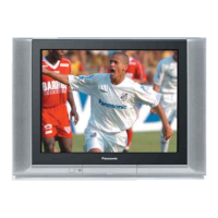
- CRT (A51JXS064X): The CRT itself is identified, indicating a conventional tube-based display.
- RGB Drive (TNPA0488): The TNPA0488 module appears to be the RGB driver board, responsible for amplifying the red, green, and blue video signals and applying them to the CRT's cathodes to produce the image. Transistors like Q351, Q352, Q354 (2SC2258RL) are typically used in these high-voltage amplifier stages.
Usage Features (Main Device):
- Remote Control Compatibility: The device is designed to be fully controllable by the EUR501310 remote control, enabling all the functions listed above.
- AV Inputs/Outputs: The "REAR AV TERMINAL" suggests the presence of external audio/video input/output jacks, allowing connection to other devices like VCRs, DVD players, or gaming consoles.
- Speaker Output: The "SPEAKER" connection indicates built-in audio output.
Maintenance Features (Main Device):
- Modular Design: The use of multiple ICs and distinct functional blocks (e.g., tuner, video processor, power supply) suggests a modular design, which simplifies troubleshooting and component replacement.
- Test Points (TPs): Various test points (e.g., TP1, TP2, TP3, TP4, TP5, TP6, TPE11, TPE12, TPE13, TPE14, TPE18, TPE30, TPE31, TPY1, TPY2) are strategically placed throughout the schematics, allowing technicians to measure voltages and signals at critical points for diagnostic purposes.
- Component Identification: All components are clearly labeled with their designators (e.g., R for resistor, C for capacitor, D for diode, Q for transistor, IC for integrated circuit) and values, facilitating repair and part ordering.
- Power Supply Diagnostics: The power supply section is detailed, enabling technicians to diagnose issues related to power delivery by checking rectifier diodes, filter capacitors, and regulator outputs.
- Signal Path Tracing: The comprehensive schematics allow for tracing signal paths from input (tuner, AV inputs) through processing stages to the display and audio outputs, aiding in pinpointing faulty sections.
- CRT-Specific Maintenance: The deflection yoke and RGB drive circuits are detailed, which are common areas for issues in CRT-based displays, allowing for targeted troubleshooting of geometry, color, and brightness problems.
In summary, this documentation provides a detailed technical blueprint for both the remote control and the main electronic device, offering essential information for understanding its operation, diagnosing faults, and performing repairs.