EasyManua.ls Logo

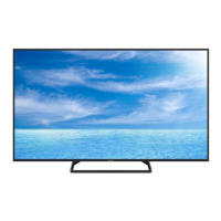
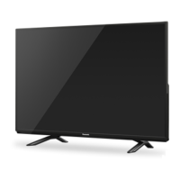
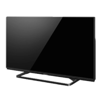
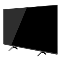
Panasonic TH-48AX670T User Manual

Panasonic TH-48AX670T
106 pages
To Next Page IconTo Next Page
Page #1 background imageLoading...
Page #1 background image
© Panasonic Corporation 2014.
ORDER NO. MTV1401264CE
LED TV
Model No. TH-48AX670T
TH-55AX670T
Chassis: LA51
Destination: THAILAND
TABLE OF CONTENTS
PAGE PAGE
1 Safety Precautions----------------------------------------------- 3
1.1. General Guidelines---------------------------------------- 3
1.1.1. Leakage Current Cold Check---------------------- 3
1.1.2. Leakage Current Hot Check (See Figure
1.) --------------------------------------------------------- 3
2 Warning-------------------------------------------------------------- 4
2.1. Prevention of Electrostatic Discharge (ESD)
to Electrostatically Sensitive (ES) Devices---------- 4
2.2. About lead free solder (PbF)---------------------------- 5
3 Service Navigation ----------------------------------------------- 6
3.1. Service Hint (TH-48AX670T) --------------------------- 6
3.2. Service Hint (TH-55AX670T) --------------------------- 7
4 Specifications ----------------------------------------------------- 8
5 Service Mode -----------------------------------------------------10
5.1. How to enter into Service Mode ----------------------10
5.1.1. Purpose ------------------------------------------------10
5.1.2. Key command ----------------------------------------10
5.1.3. How to exit---------------------------------------------10
5.1.4. Contents of adjustment mode --------------------11
5.1.5. Display of SOS History -----------------------------11
5.1.6. Exit ------------------------------------------------------ 11
5.1.7. Hotel Mode-------------------------------------------- 12
6 Troubleshooting Guide --------------------------------------- 13
6.1. Check of the IIC bus lines------------------------------ 13
6.1.1. How to access --------------------------------------- 13
6.1.2. Self-check indication only ------------------------- 13
6.1.3. Self-check indication and forced to factory
shipment setting ------------------------------------- 13
6.1.4. Exit ------------------------------------------------------ 13
6.1.5. Screen display --------------------------------------- 13
6.2. Power LED Blinking timing chart --------------------- 14
6.3. Method of detecting SOS ------------------------------ 14
6.4. LCD Panel test mode ----------------------------------- 15
6.5. No Power--------------------------------------------------- 15
7 Disassembly and Assembly Instructions--------------- 16
7.1. Speaker & H/Sink Ass’y (TH-48AX670T) ---------- 16
7.2. Speaker Fixing and Assembly
(TH-55AX670T)------------------------------------------- 17
7.3. LCD Panel Fixing & Handling Method -------------- 18
7.4. Module & LED Panel Ass’y (TH-48AX670T)------ 19

Table of Contents

Question and Answer IconNeed help?

Do you have a question about the Panasonic TH-48AX670T and is the answer not in the manual?

Panasonic TH-48AX670T Specifications

General IconGeneral
BrandPanasonic
ModelTH-48AX670T
CategoryLED TV
LanguageEnglish

Summary

Safety Precautions and Warnings

General Guidelines for Servicing

Provides essential guidelines for safe and proper servicing procedures.

Leakage Current Checks

Details procedures for performing cold and hot leakage current tests.

ESD Prevention for Sensitive Devices

Explains techniques to prevent damage from electrostatic discharge.

Lead-Free Solder Information

Provides information and precautions regarding lead-free solder usage.

Service Navigation and Model Specifics

Service Hint for TH-48AX670T

Identifies main boards and their functions for the TH-48AX670T model.

Service Hint for TH-55AX670T

Identifies main boards and their functions for the TH-55AX670T model.

Television Specifications

General TV Specifications

Details physical dimensions, mass, power, and display characteristics.

CATV Specifications

Lists specifications related to Cable Television (CATV) reception.

Service Mode Operations

Accessing and Exiting Service Mode

Instructions for entering, navigating, and exiting the service mode menu.

Service Mode Adjustment Contents

Details the adjustable parameters available within the service mode.

SOS History Display

Explains the display and clearing of System Operating Status history.

Hotel Mode Configuration

Describes settings and functions available in Hotel Mode.

Troubleshooting Guide

IIC Bus Line Checks

Procedure for checking the IIC bus lines and interpreting self-check results.

Power LED Blinking Patterns

Chart detailing power LED blinking times and corresponding error points.

SOS Detection Methods

Explains methods for detecting System Operating Status (SOS) errors.

LCD Panel Test Mode

Guide for using the LCD panel test mode to diagnose display issues.

No Power Troubleshooting

Steps to diagnose and resolve 'No Power' issues indicated by the power LED.

Disassembly and Assembly Instructions

Speaker Assembly Procedures

Instructions for disassembling and assembling speaker units and brackets.

LCD Panel Handling

Guidelines for safely fixing and handling the LCD panel.

Module and Bracket Assembly

Procedures for assembling LED panel modules and various mounting brackets.

Pedestal and Back Cover Installation

Steps for assembling TV pedestals and installing the back cover.

Measurements and Adjustments

A-Board Voltage Chart

Lists test points and specified voltages for the A-board.

Block Diagrams

Main System Block Diagram

Provides an overview of the television's main functional blocks.

Detailed Block Diagrams

Detailed schematics showing interconnections between internal components.

Wiring Connection Diagrams

Wire Dressing Procedures

Illustrations and specifications for correct wire routing and dressing.

Schematic Diagrams

A-Board Schematic Sections

Detailed circuit schematics for various sections of the A-Board.

Printed Circuit Board Layouts

A-Board PCB Layouts

Top and bottom component side layouts for the A-Board.

GK-Board and K-Board PCB Layouts

Component layouts for the GK-Board and K-Board.

P-Board PCB Layouts

Top and bottom component side layouts for the P-Board.

Exploded Views and Parts List

Parts Location Diagram

Diagram illustrating the physical location of major parts within the TV.

Packing Exploded Views

Illustrations showing the exploded views of TV packaging materials.

Comprehensive Parts List

Detailed list of all components, including part numbers and descriptions.

Related product manuals