Do you have a question about the Panasonic TH-50PV70L and is the answer not in the manual?
Steps to remove the rear and terminal covers for access.
Procedure for safely removing the P-Board, including capacitor discharge caution.
Detailed steps for disconnecting and removing the PA-Board.
Instructions for detaching the tuner unit from the chassis.
Steps for removing the DG-Board after the tuner unit is detached.
Procedure for removing the H-Board, involving tuner unit and flexible cables.
Steps for detaching the D-Board, including flexible cables.
Instructions for removing the SU-Board and its flexible cables.
Procedure for detaching the SD-Board and its flexible cable connections.
Steps to remove the SC-Board after SU and SD-Boards are detached.
Procedure for removing the SS2-Board and its flexible cable.
Steps for detaching the SS3-Board and its flexible cable.
Procedure for removing the SS-Board, involving multiple connectors.
Instructions for removing the left and right stand brackets.
Steps for removing the C1-Board, including tuner unit and stand bracket.
Procedure for detaching the C2-Board after tuner unit removal.
Steps for removing the C3-Board, including tuner unit and stand bracket.
Instructions for removing the front bracket and disconnecting a connector.
Steps to remove the G-Board and GS-Board after front bracket removal.
Procedure for detaching the speaker assemblies.
Steps for removing the S-Board metal frame and the board itself.
Procedure for detaching the K-Board and its connectors.
Instructions for carefully removing the plasma panel assembly from the cabinet.
Steps for installing the new plasma panel and reassembling the unit.
Diagnosing and resolving issues when the unit does not power on.
Troubleshooting steps for resolving a blank or distorted screen.
Identifies possible faulty PCBs for localized screen display issues.
Steps to access the service mode using the remote control.
Preparation and adjustments for driver section voltages.
Procedure for adjusting the stand down pulse T2 period.
Guidelines for PCB replacement and post-exchange voltage adjustments.
Detailed steps for adjusting sub-contrast for AV, RF, and HD signals.
Procedure for calibrating white balance for PAL signals using a color analyzer.
Steps for calibrating white balance for HD signals with a color analyzer.
Overview of major functional blocks and their interconnections.
Block diagram detailing the Power Supply unit's internal structure.
Detailed schematic of the P-Board, part one.
Detailed schematic of the P-Board, part two.
Block diagram illustrating the PA-Board's DC-DC converter functions.
Detailed schematic diagram of the PA-Board.
Block diagram illustrating AV terminal and monitor output signal paths.
Block diagram showing audio processing and tuner interface connections.
Detailed schematic of the H-Board, part one.
Detailed schematic of the H-Board, part two.
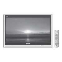
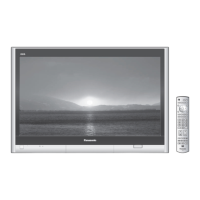
Visual representation of the product's components for identification.
| Screen Size | 50 inches |
|---|---|
| Display Technology | Plasma |
| Resolution | 1366 x 768 |
| Aspect Ratio | 16:9 |
| Brightness | 1500 cd/m² |
| Response Time | 0.001 ms |
| Contrast Ratio | 10000:1 |
| Input Ports | HDMI, Component, Composite, S-Video, VGA |