48 49
4
PRODUCTS
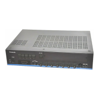
WA-MA120N/WA-MA240N
4
PRODUCTS
WA-MA120N/WA-MA240N
CONCEPT SYSTEM EXAMPLES CONNECTIONS PRODUCTS BLOCK DIAGRAMS
CONCEPTSYSTEM EXAMPLESCONNECTIONSPRODUCTSBLOCK DIAGRAMS
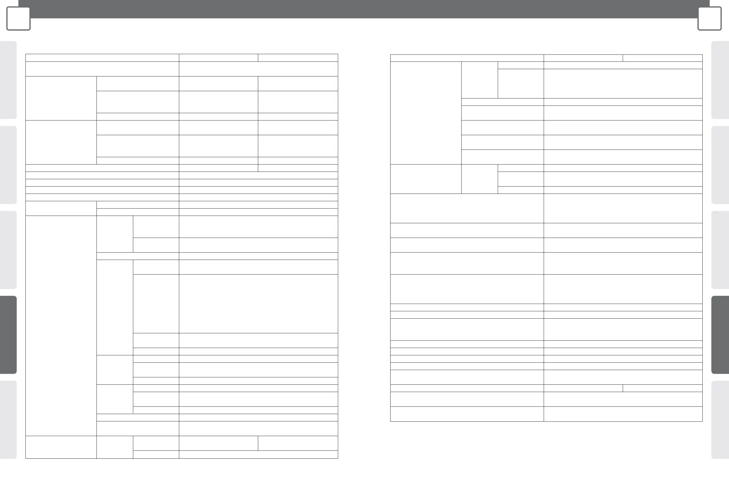
SPECIFICATIONS
Model No. WA-MA120N WA-MA240N
Power Source AC:110 V-120 V or 220 V-240 V (selectable), 50 Hz /60 Hz
DC:+24 V (Battery), M3 screw terminal
*1
Power Consumption (AC) Non-operation mode 25 W 30 W
(standby)
Under normal operating 125 W 225 W
conditions according to
IEC60065
With rated output signal 360 W 755 W
Current Consumption (DC) Non-operation mode 0.5 A 0.5 A
(standby)
Under normal operating 4.5 A 8.5 A
conditions according to
IEC60065
With rated output signal 10 A 20 A
Rated Output 120 W 240 W
Frequency Response 50 Hz-15 kHz
Distortion Less than 1 % at 1 kHz rated output
Signal- to-Noise Ratio More than 60 dB (-22 dBV input to ZONE output)
Tone Control Bass:±10 dB at 100 Hz, Treble:±10 dB at 10 kHz
Volume Control EMG 0 dB to -20 dB
Others 0 dB to – ∞ (off)
Audio Signal Input INPUT 1-3 Audio Signal MIC:–65 dBV/LINE:–22 dBV (selectable)
Connectors 5 kΩ, electronically balanced, XLR-3-11 type connector
(female)
Control No-voltage make contact input, open voltage:+5 VDC,
(Only INPUT 1) short-circuit current:under 1 mA, Push-in terminal
*3
LINE 1,2 Jacks –22 dBV, 10 kΩ, unbalanced, RCA pin jack x2 (monaural)
RM Terminal Audio Signal RM:–22 dBV/MIC:–65 dBV (selectable)
(Remote 10 kΩ, electronically balanced
Microphone Control No-voltage make contact input, open voltage:+5 V DC, short-
Input) circuit current:under 1 mA
1 CALL (2-channel announcement select)
2 BC (activation control of announcement)
3 ALL CALL (activation control of all-zone announcement)
4 Z1 (zone 1 select)
5 Z2 (zone 2 select)
6 Z3 (zone 3 select)
Power DC+24 V, MAX 200 mA
Supply (Up to 4 Remote Microphones (WR-210AE) can be connected)
Connector Push-in terminal
*3
TEL PAGING Audio Signal –22 dBV, 10 kΩ, electronically balanced
Terminals Control No-voltage make contact input, open voltage:+5 V DC,
(Telephone short-circuit current:under 1 mA
Paging Input) Connector Push-in terminal
*3
EMG Terminals
Audio Signal 0 dBV, 10 kΩ, electronically balanced
(Emergency
Control No-voltage make contact input, open voltage:+5 V DC,
Equipment
short-circuit current:under 1 mA
Input)
Connector Push-in terminal
*3
INS IN Jack (Insertion Input) 0 dBV, 100 kΩ, unbalanced, RCA pin jack
ZONE 1 CALL IN 100 V or 70 V balanced, M3 screw terminal
*2
(for 2-channel Announcement)
Audio Signal Output ZONE 1-3, Output Voltage/ 100 V/83 Ω 100 V/42 Ω
DIRECT OUT Impedance (changeable to 70 V/42 Ω) (changeable to 70 V/21 Ω)
Terminals Connector M3 screw terminal
*2
Model No. WA-MA120N WA-MA240N
Audio Signal Output
SP4 Ω
Impedance 4 Ω
Terminal (Low
Connector M3 screw terminal
*2
Impedance
Loudspeaker
Output)
LINE OUT Jack 0 dBV, 10 kΩ adapted, unbalanced, RCA pin jack
REC OUT Jack 0 dBV, 10 kΩ adapted, unbalanced, RCA pin jack x2
(monaural)
INS OUT Jack 0 dBV, 10 kΩ adapted, unbalanced, RCA pin jack
(Insertion Output)
INS THRU Jack Through output from INS IN, unbalanced, RCA pin jack
(Insertion Through Output)
INPUT D-OUT Jack 0 dBV, 10 kΩ adapted, unbalanced, RCA pin jack
(Input Direct Output) (Output for 2-channel announcement from INPUT 1 or RM)
Audio Signal In/Out ALL CALL Audio Signal –20 dBV balanced
for expansion BUS Control Activation control of all-zone announcement
IN/THRU 1 from EMG 2 from TEL/INPUT 1 3 from RM
Connectors Connector 9-pin female D-sub connector x2 (in/through)
CALL SIGN CNT Terminals No-voltage make contact input, open voltage:+5 V DC,
(Activation control of built-in call tones) short-circuit current:under 1mA, Push-in terminal
*3
,
1:4-Tone (Up), 2:4-Tone (Down), 3:2-Tone (Down)
One-shot make:single playback, at make:repeat playback
OPERATE ON/OFF Terminals No-voltage make contact input, open voltage:+5 V DC, short-
circuit current:under 1 mA, M3 screw terminal
*2
OPERATE LINK Terminal Open collector output, withstand voltage:+30 V DC, operating
current:under 50 mA, M3 screw terminal
*2
ATT OVERRIDE Terminals No-voltage make contact output (transfer type relay),
withstand voltage: 30 V DC, 250 V AC, contact current:under
3A (DC/AC), M3 screw terminal
*2
Announcement Priority Control (Input Priority at 1-Channel Priority 1:EMG
Announcement) Priority 2:TEL PAGING, INPUT 1
Priority 3:RM
Priority 4:INPUT 2,3, LINE 1,2
Priority Indicator EMG, TEL, RM
PA OUTPUT LEVEL Meter 5 points, -30/-20/-15/-8/0
Other Functions •
2-channel announcement by Remote Microphone or paging microphone.
•
Zone output extension by connecting plural units. (up to 30 zones by 10 units)
•
All-zone announcement in various operating areas. (up to 10 areas)
Phantom Power Supply for INPUT 1-3 +16 V, on/off selectable individually
Power Supply for External Equipment DC+24 V, MAX 200 mA, M3 screw terminal
*1
Cooling Fan 3 modes;Stop/Low speed/High speed
Operating Temperature 0 °C-+45 °C (32 °F -113 °F)
Dimensions
420 mm (W) x 146 mm (H) x 404 mm (D){13-17/32" (W) x 5-3/4" (H) x 15-29/32" (D)}
(Height includes rubber feet and depth includes projections such as rear protect cover.)
Weight (Approx.) 14 kg (30.87 lbs.) 15.5 kg (34.17 lbs.)
Finish Panel:Gun Metallic painting (ABS Resin)
Case: black painting, Munsell N2.5 or equivalent (steel plate)
Optional Products • Remote Microphone:WR-210AE
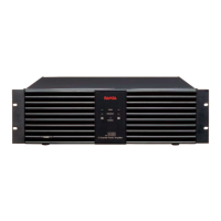
• Booster Power Amplifier:WA-BA240N (240 W)
0 dB = 1 V
*1 Barrier distance:8.12 mm, Suitable cable gauge:AWG18-14 (Solid)/AWG14 (Stranded)
*2 Barrier distance:6.27 mm, Suitable cable gauge:AWG22-14
*3 Suitable cable gauge:AWG22-14
*
Dimensions and weight indicated are approximate.Specifications are subject to change without notice.