16
● MODE Switch Setting for System Example 2
The MODE switch needs to be set prior to operating a sys-
tem connected as shown in Example 2.
Bit 3 should be set to OFF.
Bit 5 should be set to OFF when the controller is placed
in an intermediate position, or set to ON when it is con-
nected at the chain end.
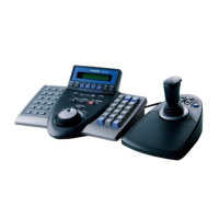
■ Controller Number Setting (PS
•
Data)
A 10-position rotary switches provided on the rear for spec-
ifying the unit number of the WV-CU360C controller in a
PS
•
Data system.
1. Remove the DC plug from the rear of the controller.
2. Use a screw driver to rotate the switch so that the arrow
comes to the number you wish.
3. Connect the DC plug to the controller.
Notes:
• Set the switch to #1 when a single controller is used in
the system.
• Specify a unique number for each controller when con-
necting multiple controllers in the system. One con-
troller within the multiple controller system must be
assigned the number 1.
• Positions #0 and #9 are reserved and cannot be used.
 Loading...