User Manual For CYCLONE FX Programmers 22
Note: If these jumpers are not set correctly, the Cyclone will not function as intended.
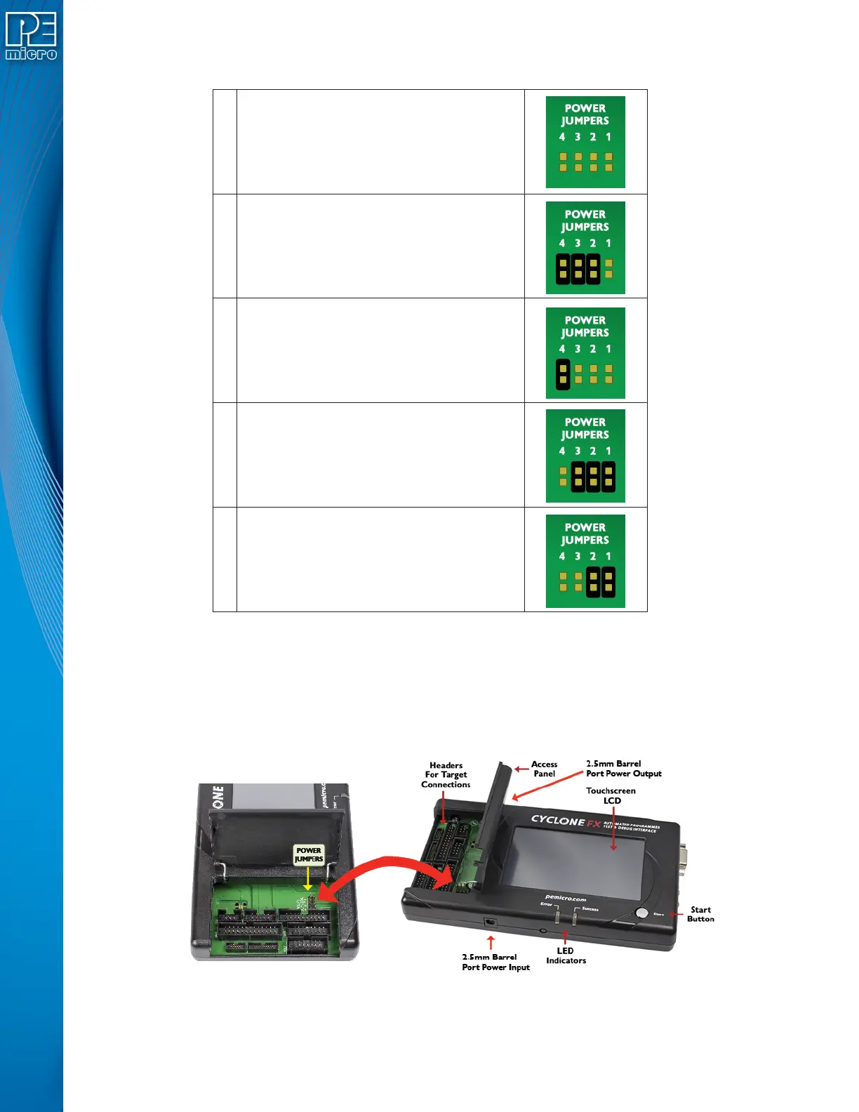
Figure 4-2: Cyclone Power Schemes & Corresponding Jumper Settings
The bottom edge of the CYCLONE FX has a Power In jack for externally provided power, and the
top edge of the Cyclone has Power Out jack, for when power schemes including these are used
(see Figure 4-3). One of the provided ribbon cables is connected to the appropriate debug header
based on the specific target architecture.
Figure 4-3: Cyclone Hardware Features: Power Jumpers and Target Headers
The power settings that are set by the jumpers are a physical connection and take precedence.
1 Target is powered independently
2
Power provided externally (center +) and
managed by Cyclone, power out to debug
ribbon cable.
3
Power provided externally (center +) and
managed by Cyclone, power out to 2.5 mm
output jack (center +)
4
Power provided by Cyclone, power out to
debug ribbon cable
5
Power provided by Cyclone, power out to
2.5 mm output jack (center +)
 Loading...