SECTION 3.
CONFIGURATION
PRINTER DIP SWITCH CONFIGURATION
DIP Switch Panels
There are two DIP switches (DSW2 and DSW3) located underneath a snap-on cover
on the front panel. These switches can be used to set:
•
Thermal transfer or direct thermal mode
•
Label sensor enable/disable
•
Head check mode
•
Hex dump mode
• Single job or multi-job buffer
• Operation mode
In addition, a third DIP switch is located on the RS232C Serial Adapter card and is
used to set the RS232C transmit/receive parameters. (NOTE: Not factory standard)
Each switch is an eight section “toggle” switch. The ON position is always to the top.
To set the switches, first power the unit OFF, then position the DIP switches.
Finally, after placing the switches in the desired positions, power the printer back
on. The switch settings are read by the printer electronics during the power up
sequence. They will not become effective until the power is cycled.
Printer Set Up
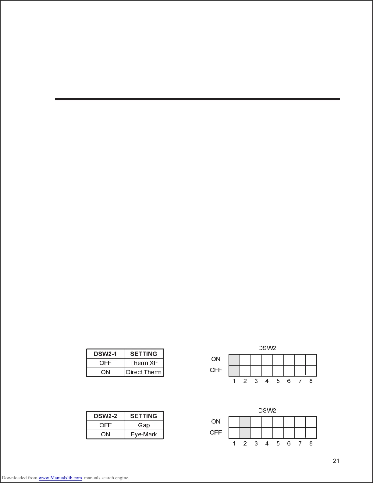
Print Mode Selection (DSW2-1). Selects between direct thermal printing on
thermally sensitive paper and thermal transfer printing using a ribbon.
Sensor Type Selection (DSW2-2). Selects between the use of a label gap or a
reflective Eye-Mark detector. See page 20 for the location of these sensors.
21
DSW2-1 SETTING
OFF Therm Xfr
ON Direct Therm
12345678
ON
OFF
DSW2
DSW2-2 SETTING
OFF Gap
ON Eye-Mark
12345678
ON
OFF
DSW2