PAR T GOLF DOUBLE EAGLE INSTALLATION AND MAINTENANCE MANUAL
SECTION E ENJOYING YOUR SIMULATOR
E4
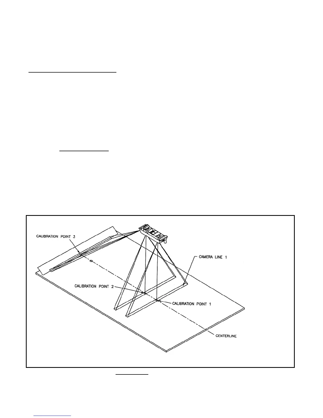
Locate and Mark
Calibration Point #3
–
Using measuring tape, locate the exact middle of the platform exactly
on the front of the screen's black flap. It should be directly behind the
ball cup. Then using a black marker, mark the point and follow the
procedure outlined below.
CAMERA CALIBRATION
STEP 2 Loading calibration mode on
the touch screen or projected
image.
–
From the selection screen, select DOUBLE EAGLE, then SENSOR
ADJUST. A series of lines and numbers should be displayed on the
large screen. Program Key must be turned horizontal. The Program Key
is above and to the left of the keyboard.
STEP 3 Place Object in Near
Camera's field of vision
–
Place your hand on the floor near the Tri-Turf, then slide it slowly
toward the screen. When you cross camera #1’s field of vision, you
will see a graphical representation of the object in camera #1. This will
be displayed directly on the screen. It will also display a number and a
size for the object in the camera. This will be the same for all cameras.
Meaning of Numbers
Drawing 10B
–
Each camera continuously monitors its narrow "Camera Line", which
is located directly in front of its lens and parallel to the screen. The
numbers represent data from the camera. They refer to the location of
objects on the camera's camera line.
This narrow camera line is calibrated from #0 (far left) to #512 (far
right), with #256 being at the center.
When the camera is properly aimed, the message on the screen will
read 256 and a size number (The size number depends on the
strength of the signal of the camera).
Drawing 10B Camera Field of Vision



 To Next Page