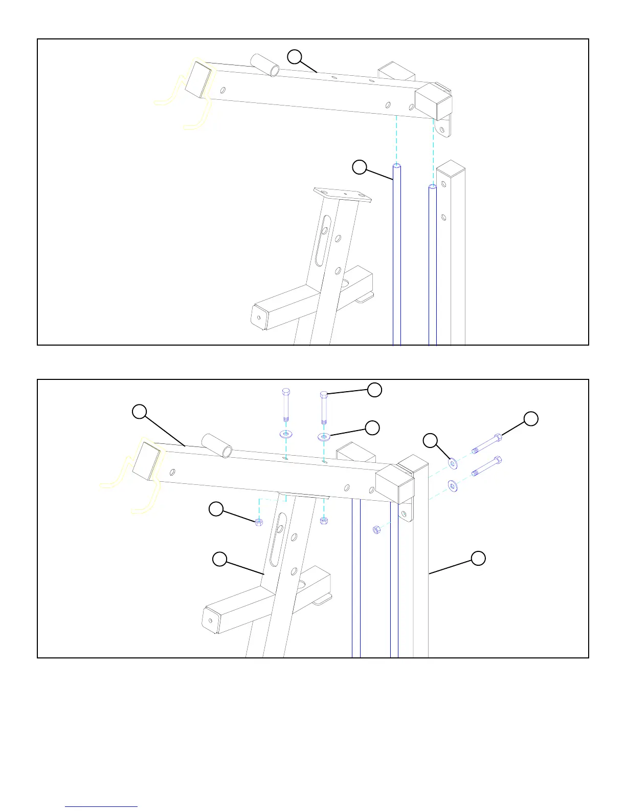
FIGURE 4
6
STEP 4
FIGURE 5
STEP 5
• Swing the GUIDE RODS (16) under the TOP BOOM (7) as shown on FIGURE 4.
• Loosely assemble the TOP BOOM (7) to the REAR UPRIGHT (9) using two 1/2 X 3” BOLTS (46), two 1/2” WASHERS (39), and
one 1/2” LOCKNUT (40). See FIGURE 5.
• Loosely assemble the TOP BOOM (7) to the FRONT UPRIGHT (2) using two 1/2 X 4” BOLTS (47), two 1/2” WASHERS (39), and
two 1/2” LOCKNUTS (40). See FIGURE 5.
• At this time, securely tighten all frame connections in this order: REAR UPRIGHT (9) to TOP BOOM (7), REAR UPRIGHT (9) to
BASE (8), TOP BOOM (7) to FRONT UPRIGHT (2), and FRONT UPRIGHT (2) to BASE (8).
16
7
39
9
7
40
2
39
47 1/2 X 4”
46 1/2 X 3”
 Loading...
