5
FIGURE 3
0
1
2
345
6
1/2 1/2 1/2 1/2 1/2 1/2
STEP 3
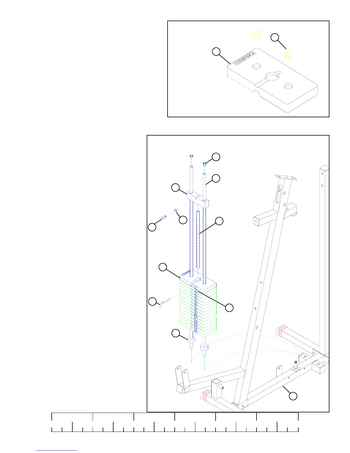
FIGURE 2
• Insert two WEIGHT PLATE BUSHINGS (23) into the
“PARABODY” side of each of the fifteen WEIGHT
PLATES (58) as shown in FIGURE 2.
STEP 2
• Insert two GUIDE RODS (16) into the BASE (8)
as shown on FIGURE 3. (NOTE: Lubricate
GUIDE RODS (16) with silicon or teflon spray
available at most hardware stores.)
• Slide two WEIGHT STACK CUSHIONS (53)
down over the GUIDE RODS (16).
• Securely assemble the WEIGHT STACK SHAFT
(21) to the HEAD PLATE (20) using one 3/8 X 1-
1/4” BOLT (44) and one 3/8” WASHER (38).
• Using EXTREME CARE slide all fifteen
WEIGHT PLATES (58) down over the GUIDE
RODS (16) on to the WEIGHT STACK CUSH-
IONS (53). Make sure that the keyholes of the
WEIGHT PLATES (58) are all facing the right
way.
• Attach the WEIGHT STACK LABELS (17) to the
weight stack. Also insert the WEIGHT STACK
SELECTOR PIN (34) into the first WEIGHT
PLATE (58) of the weight stack.
• Slide the head plate assembly down over the
GUIDE RODS (16) onto the weight stack.
23
20
16
21
38
34
58
58
53
8
17
44 3/8 X 1-1/4”
• Insert two CAP PLUGS (54) into the top of the
GUIDE RODS (16).
54
 Loading...
