FIGURE 7
8
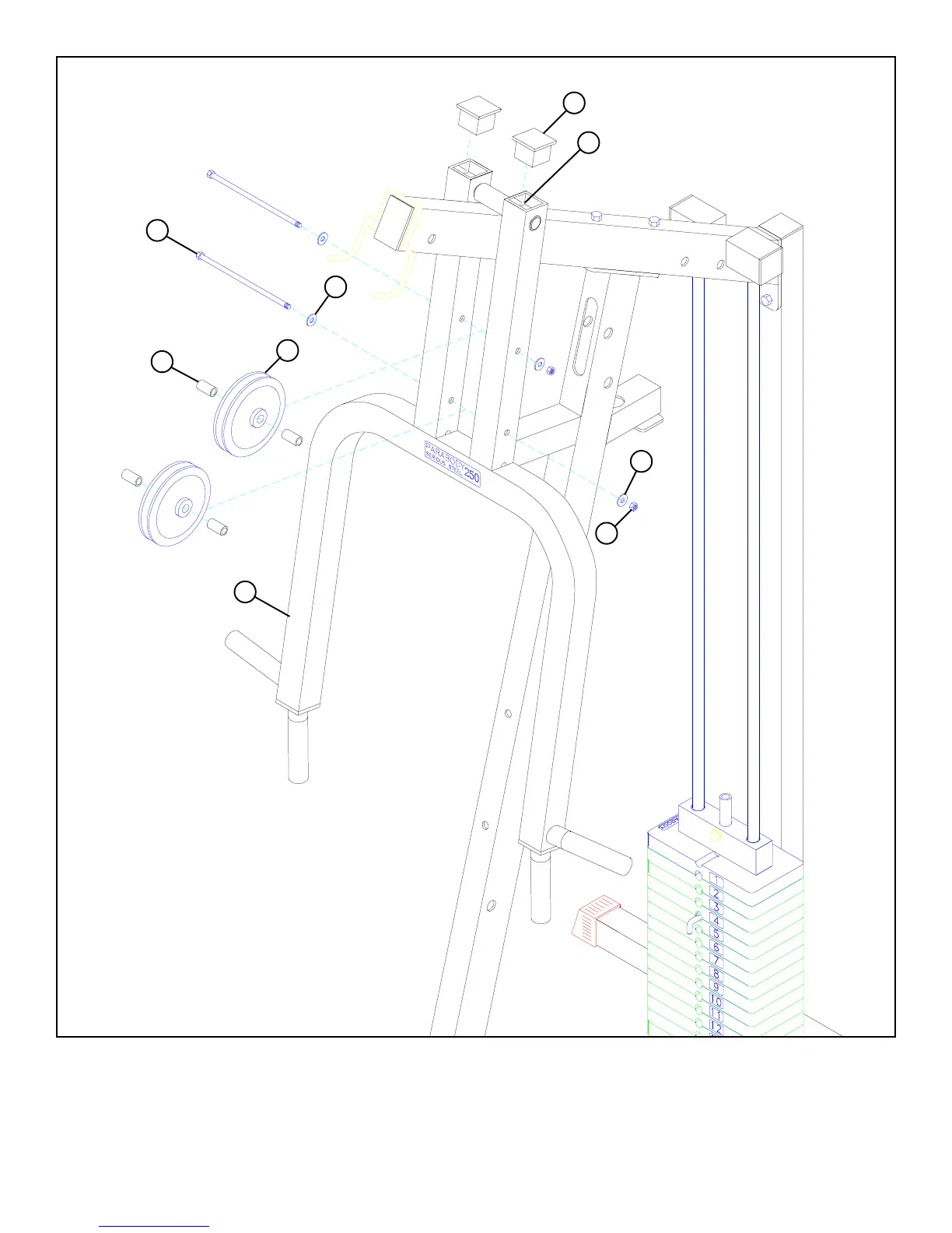
• Loosely assemble two 4-1/2” PULLEYS (18) to the PRESS ARM (3) using two 3/8 X 7-1/2” BOLTS (51), four 3/8” WASHERS
(38), four 3/8 X 1” SPACERS (32), and two 3/8” LOW HEIGHT LOCK NUTS (43) as shown in FIGURE 7. Once both PULLEYS
are installed, you may securely tighten these two connections.
• Securely tighten the two SET SCREWS (50) and insert two 2” SQ. END CAPS (56) into open ends of the PRESS ARM (3) as shown
in FIGURE 7.
STEP 7
3/8 X 7-1/2” 51
56
50
38
38
43 LOW
HEIGHT
32
18
3
 Loading...
