9
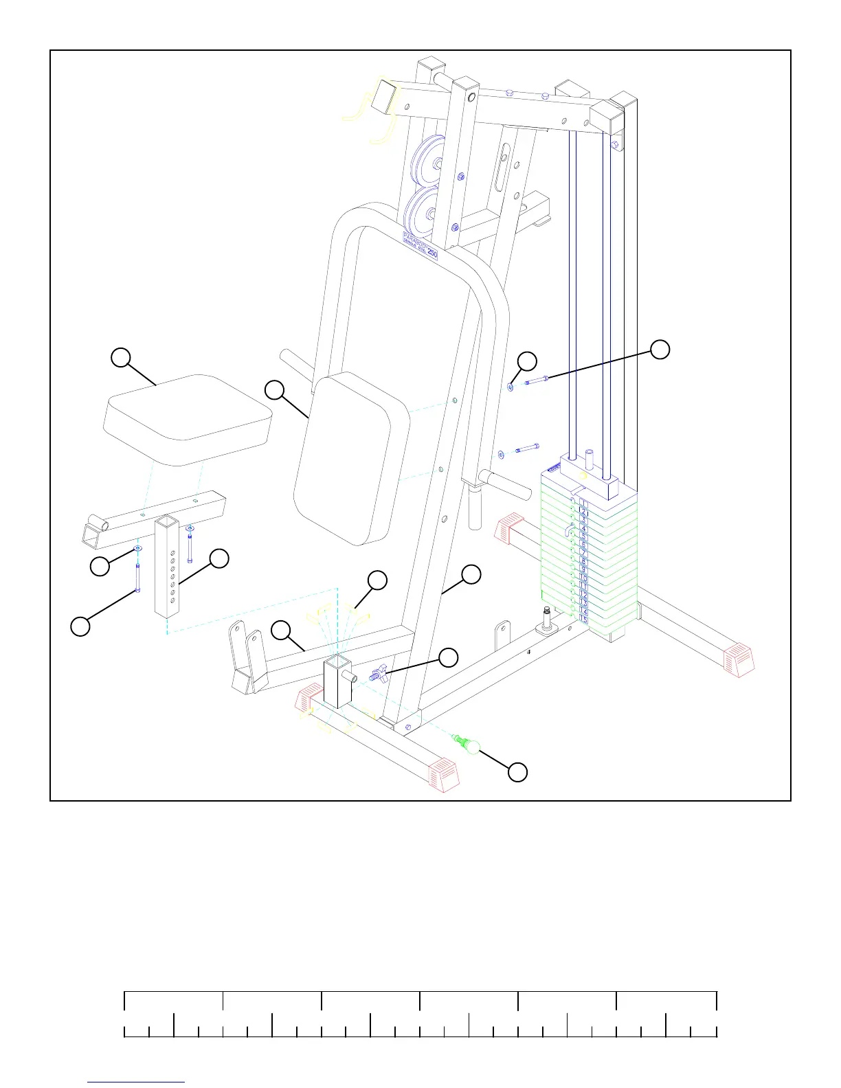
FIGURE 8
STEP 8
• Securely assemble one SPRING PIN ASSEMBLY (35) and one 3 PRONG KNOB (33) to the FRONT UPRIGHT (2) as shown.
• Apply eight PARAGLIDES (57) to the INSIDE of the tube on the FRONT UPRIGHT (2) as shown.
0
1
2
345
6
1/2 1/2 1/2 1/2 1/2 1/2
• Securely assemble one SEAT PAD (12) to the PRESS SEAT (4) using two 3/8 X 2-3/4” BOLTS (48) and two 3/8” WASHERS (38)
as shown in FIGURE 8.
• Insert the PRESS SEAT ASSEMBLY into the FRONT UPRIGHT (2) as shown. The PRESS SEAT height can be adjusted using the
SPRING PIN (35) and can be secured with the 3 PRONG KNOB (33).
• Securely assemble one SEAT PAD (12) to the FRONT UPRIGHT (2) using two 3/8 X 3-3/4” BOLTS (45) and two 3/8”
WASHERS (38) as shown in FIGURE 8.
48 3/8 X 2-3/4”
45 3/8 X 3-3/4”
57
38
4
2
33
38
12
35
12
2
 Loading...
