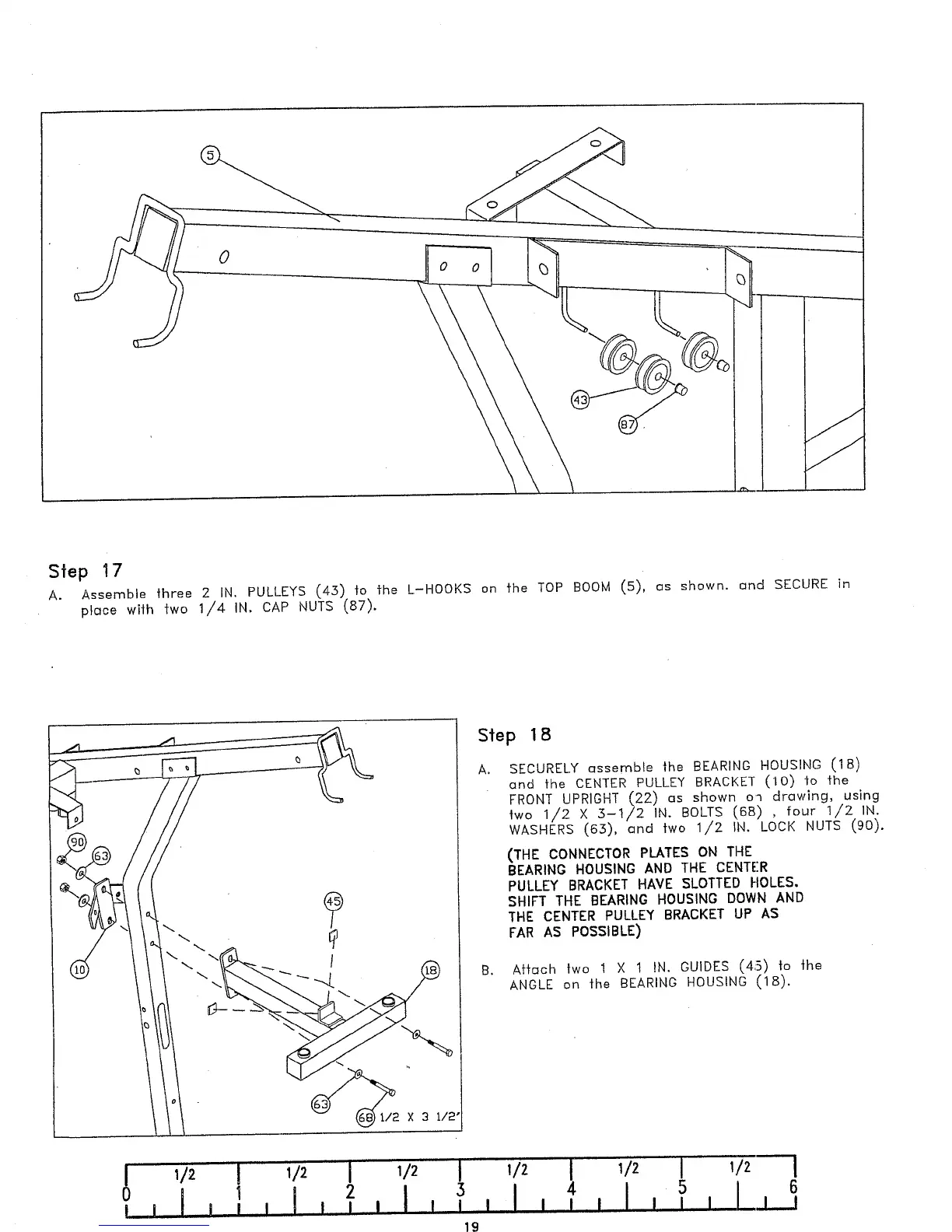
Step 1 7
A.
Assemble three 2 IN. PULLEYS (43) to the L-HOOKS on the TOP BOOM (5), us shown, and SECURE
piece with two 1/4 IN. CAP NUTS (87).
1/2
I 1/2
I
1/2
2
I
1 ~ I I
I
Step 1 8
A. SECURELY assemble the BEARING HOUSING (18)
and the CENTER PULLEY BRACKET (10) fo the
FRONT UPRIGHT (22) as shown oq drawing, using
two 1,/2 X 3-1/2 IN. BOLTS (68) , four 1/2 IN.
WASHERS (63), and two 1/2 IN. LOCK NUTS (90).
(THE CONNECTOR PLATES ON THE
BEARING HOUSING AND THE CENTER
PULLEY BRACKET HAVE SLOTTEr) HOLES,
SHIFT THE BEARING HOUSING DOWN AND
THE CENTER PULLEY BRACKET UP AS
FAR AS POSSIBLE)
B. Attach two 1 X t IN. GUIDES (4i5) to the
ANGLE on the BEARING HOUSING (18).
I I
 Loading...