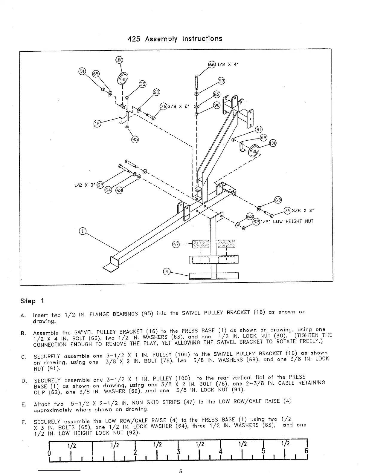
425 Assembly Instructions
13/8 X
t/2" LD~/ HE’.[15HT NUT
Step 1
A. Insert two 1/2 IN. FLANGE BEARINGS (9.5) into the SWIVEL PULLEY BRACKET (16) os shown
drawing.
B.
Assemble the SWIVEL PULLEY BRACKET (16) to the PRESS BASE (1) as shown on drowing, using
1/2 X 4 IN. BOLT (66), two 1/2 IN. WASHERS (63), and one 1/2 IN. LOCK NUT (90). (TIGHTEN
CONNECTION ENOUGH TO REMO~E THE PLAY, YET ALLOWING THE SWIVEL BRACKET TO ROTATE FREELY.)
C. SECURELY essemble one 3-1/2 X 1 IN. PULLEY (100) to the SWIVEL PULLEY BRACKET (16) as shown
on drawing, using one 3/8 X 2 IN. BOLT (76), two 3/8 IN. WASHERS (69), and one 3/8 IN.
NUT (91).
D. SECURELY essemble one 3-1/2 X 1 IN. PULLEY (100) to the rear vertical fiat of the PRESS
BASE (1) as shown on drawing, using one 3/8 X 2 IN. BOLT (76), one 2-3/8 IN. CABLE RETAINING
CLIP (62), one .3/8 IN. WASHER (69), .and one 3/8 IN. LOCK NUT (91).
E. Attach two 5-1/2 X 2-1/2 IN. NON SKID STRIPS (47) fo the LOW ROW/CALF RAISE
approximately where shown on drawing.
F.
SECURELY assemble the LOW ROW/CALF RAISE (4) |o the PRESS BASE (1 using two 1/2.
X :5 IN. BOLTS (65), one 1/2 IN. LOCK WASHER (64), three 1/2 IN. WASHERS (65),
1/2 IN. LOW HEIGHT LOCK NUT (92).
5 6
2 I I I , ] , I , ] I I I L I ,,I1 l I I I
i i I I I I
end one