318 X 2-3/4"~
112 X 3-t12"
1 /
/
I /
/
I /
/
I
/ //
//
/
/
/
3/8 X 2"
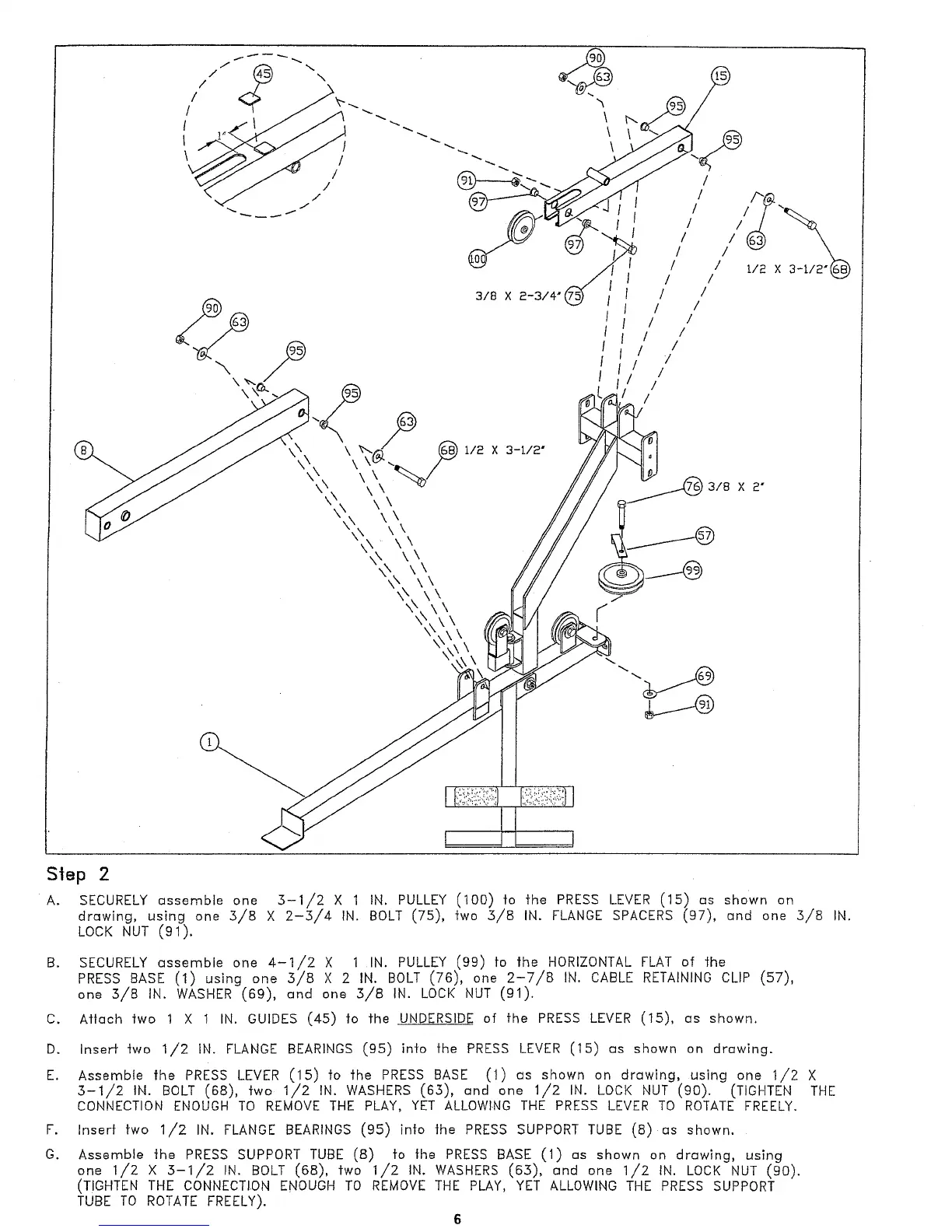
S|ep 2
A. SECURELY assemble one 3-1/2 X 1 IN. PULLEY (100) to the PRESS LEVER (15) as shown
drawing, using one 5/8 X 2-5/4 IN. BOLT (75), fwo 5/8 IN. FLANGE SPACERS (97), and one 5/8
LOCK NUT (91).
B. SECURELY assemble one 4-1/2 X 1 IN. PULLEY (99) fo the HORIZONTAL FLAT of ~he
PRESS BASE (1) using one 5/8 X 2 IN. BOLT (76), one 2-7/8 IN. CABLE RETAINING CLIP (57),
one 5/8 IN. WASHER (69), and one 5/B IN. LOCK NUT (91).
C. Aflach two 1 X 1 IN. GUIDES (45) to fhe UNDERSIDE of fhe PRESS LEVER (15), as shown.
D. Inserf two 1/2 IN. FLANGE BEARINGS (95) into fhe PRESS LEVER (15) as shown on drawing.
E. Assemble the PRESS LEVER (15) to the PRESS BASE (1) us shown on drawing, using one 1/2
5-1/2 IN. BOLT (68), two 1/2 IN. WASHERS (65), and one 1/2 IN. LOCK NUT (90). (TIGHTEN
CONNECTION ENOUGH TO REMOVE THE PLAY, YET ALLOWING THE PRESS LEVER TO ROTATE FREELY.
F.
Inserf fwo 1/2 IN. FLANGE BEARINGS (95) in|o the PRESS SUPPORT TUBE (8) as shown.
G. Assemble the PRESS SUPPORT TUBE (8) fo the PRESS BASE (1) as shown on drawing, using
one 1/2 X 5-1//2 IN. BOLT (68), fwo 1/2 IN. WASHERS (65), and one 1/2 IN. LOCK NUT (90).
(TIGHTEN THE CONNECTION ENOUGH TO REMOVE THE PLAY, YET ALLOWING THE PRESS SUPPORT
TUBE TO ROTATE FREELY).
6