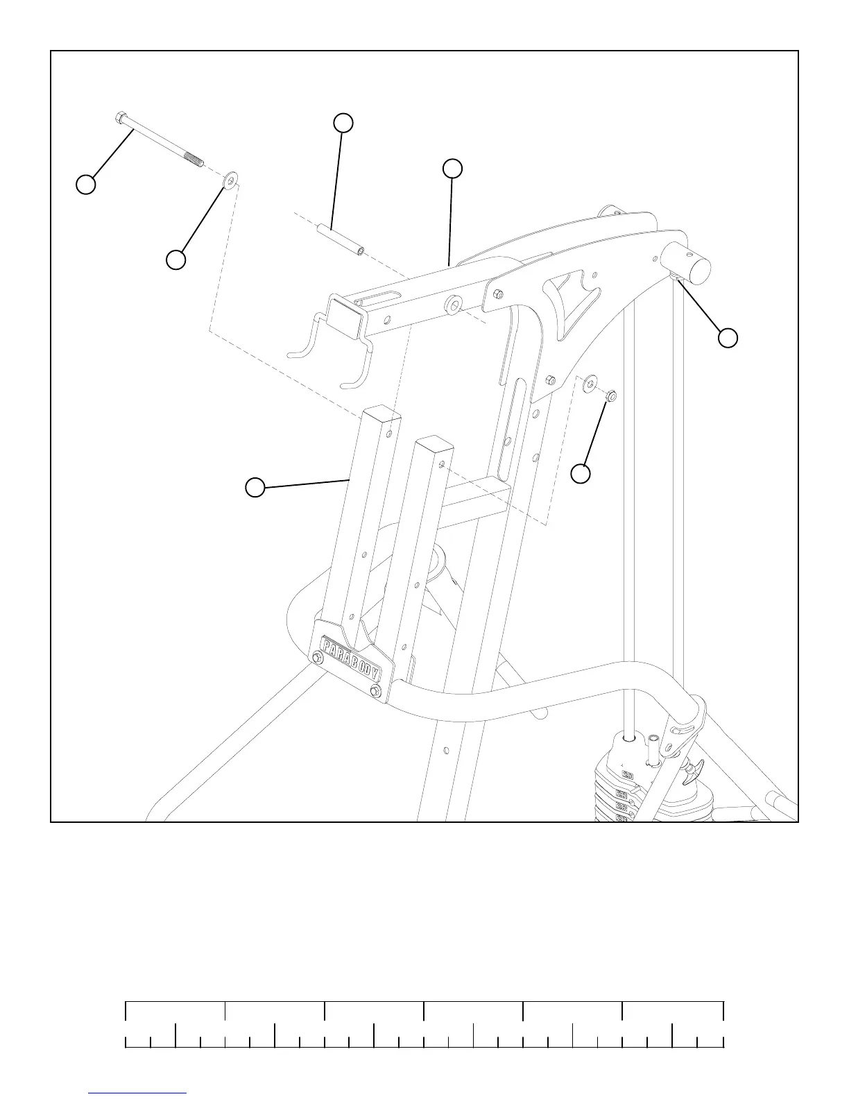
FIGURE 9
11
0
1
2
345
6
1/2 1/2 1/2 1/2 1/2 1/2
STEP 9
• SECURELY TIGHTEN ALL FRAME CONNECTION BEFORE PROCEEDING TO NEXT STEP
33
37
60
48
9
1/2 X 8-3/4”
SECURELY
TIGHTEN
• SECURELY TIGHTEN top of both SHAFT COLLARS (48) flush to bottom of both BOOM PLATES (4),(5)
1
40
• Assemble the PRIMARY PIVOT (9) of the PRESS ARM ASSEMBLY to the top of the FRAME (1) using 1/2 X 8-3/4” BOLT (33),
two 1/2” FLAT WASHERS (37) and 1/2” LOCK NUT (60).
• Insert one 3/4 x 4” SHAFT (40) into both 3/4” FLANGE BEARINGS on FRAME (1)
 Loading...


