12
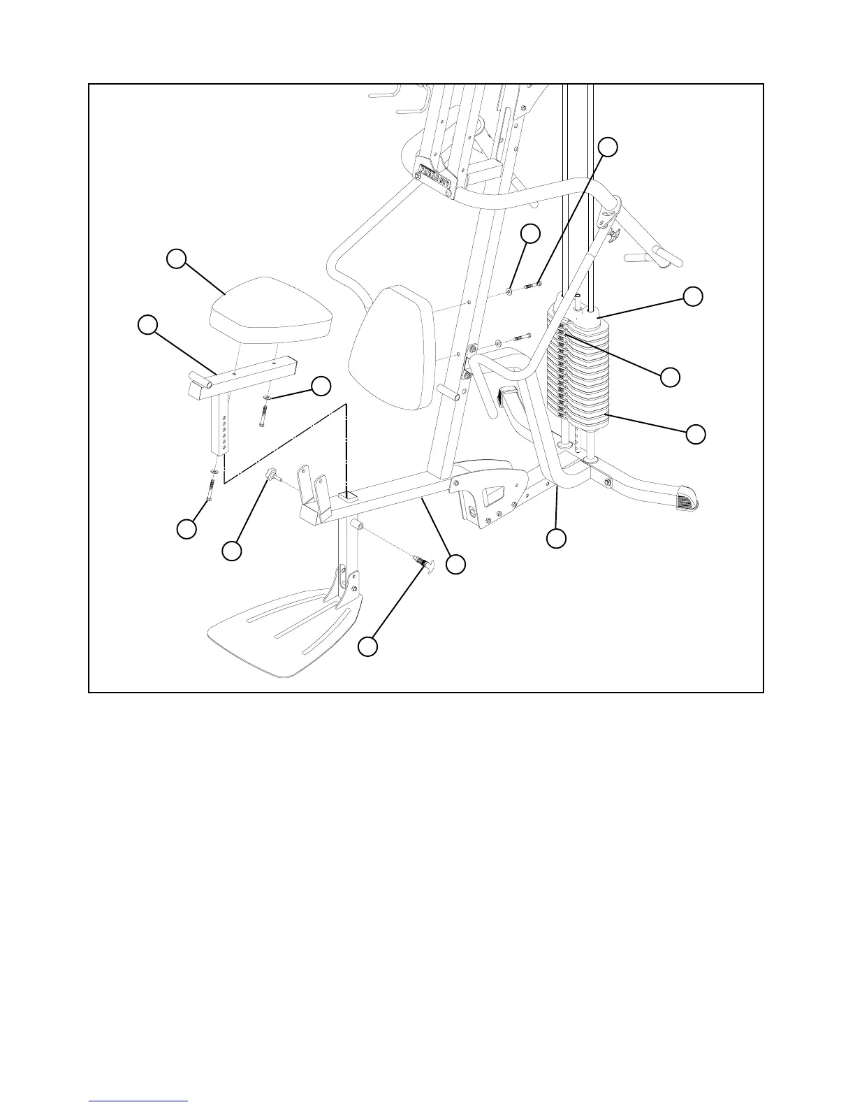
STEP 10:
• Securely tighten the SPRING PIN (50) to the FRAME (1) and hand tighten the STAR KNOB (52)
• Securely assemble one SEAT PAD (13) to the SEAT ADJUSTMENT (10) using two 3/8 X 3” BOLTS (29) and two
3/8” WASHERS (36) as shown.
FIGURE 10
• Securely assemble one SEAT PAD (13) to the FRAME (1) using two 3/8 X 3” BOLTS (29) and two 3/8” WASHERS (36)
as shown. The top connection of the FRAME BRACE (64) may have to be loosened and then re-tightened after SEAT
PAD (13) is tighten
• Gently insert SEAT ADJUSTMENT (10) into tube located on FRAME (1)
• Apply WEIGHT STACK LABELS (61) to WEIGHTS (22) and HEAD PLATE (19) as shown in FIGURE 10.
Begin with number one at the HEAD PLATE (19) with larger numbers in consecutive order towards bottom of weight stack.
1
29
36
13
52
50
10
3/8 X 3”
61
19
22
64
3/8 X 3”
29
36
 Loading...


