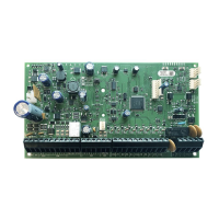
DGP-848 Control Panel 9
3 Programming Methods
The Digiplex control panel can be programmed using the WinLoad
software, the Paradox Memory Key, or manually by using an LCD
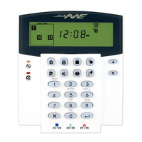
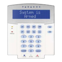
(DGP2-641BL) or Grafica (DNE-K07) keypad. We highly
recommend programming the control panel with WinLoad as it
greatly simplifies the process and reduces potential data errors.
Please refer to WinLoad Software on page 44. for details on how to
set up the control panel to function with WinLoad.
You can also copy the programmed contents of one Digiplex
control panel into as many Digiplex control panels as you need by
using the Paradox Memory Key (see section 3.7 on page 10). Each
control panel is programmed in less than 5 seconds.
Keypads and other modules can also be programmed easily by
using Module Broadcast (see section 12.12 on page 37). Once a
module is programmed, its sections can be sent to other similar
modules through the combus.
3.1 Panel Programming Mode
Use the Programming Guide to keep track of which sections were
programmed and how. In order to program anything in the Digiplex
control panel you must enter panel programming mode.
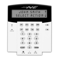
For LCD keypads:
After entering the required data, either the control panel will
automatically save the data and advance to the next section, or
you must press the [
ENTER] key to save the data and advance to
the next section. Press the [CLEAR] key to revert to the preceding
step or to erase the current data.
For Grafica keypads:
After entering the required data, press Grafica’s center action key
(Save) to save the data and advance to the next section. Press the
right action key (Exit) to revert to the preceding step or press the
left action key (Clear) to erase the current data.
3.2 Module Programming Mode
All modules connected to the combus are programmed through an
LCD (DGP2-641BL) or Grafica (DNE-K07) keypad in the system.
To do so, simply enter Module Programming Mode as shown
below.
The control panel will redirect all programming to the selected module.
To exit Module Programming Mode, press the [
CLEAR] key on LCD
keypads, or the right action key (Exit) on Grafica keypads, as many
times as needed to return to the desired screen. Please note that a
module's serial number can be located on the module's PC board or it
may already be recorded in the module's Installation Guide.
3.3 Feature Select Programming
Most of the Digiplex control panel options are programmed using
the Feature Select Method.
For LCD keypads:
Each number from 1 to 8 corresponds to a specific feature or
option. Set these options by turning the number corresponding to
the feature ON or OFF. The option is considered ON when the
number appears within the brackets. Turn options ON and OFF by
pressing the corresponding keys on the keypad. Press the keys as
many times as you need to select the desired options and then
press [
ENTER] to save.
For Grafica keypads:
Select or clear the check boxes pertaining to the options or
features that you wish to enable or disable. You can also set the
options by pressing the corresponding keys on the keypad. The
feature is considered ON when its check box is selected. To save
the settings, press Grafica’s center action key (Save).
3.4 Decimal Programming
Certain sections may require the entry of a 3-digit decimal value
from 000 to 255.
3.5 Hexadecimal Programming
Certain sections may require the entry of one or more Hexadecimal
values from 0 to F.
For LCD keypads:
For Grafica keypads:
T
O PROGRAM IN PANEL PROGRAMMING MODE:
1) Press and hold the [0] key.
2) Enter the [
INSTALLER CODE] (Default is 000000).
3) Enter the 3-digit [
SECTION].
Every feature and or option is programmed in a three-digit
section starting at [001].
4) Enter the required [
DATA].
The type of data required will be detailed in the Programming
Guide and/or explained in the appropriate sections of this
manual.
TO PROGRAM IN MODULE PROGRAMMING MODE:
1) Press & hold the [0] key.
2) Enter the [
INSTALLER CODE] (Default is 000000).
3) Enter section [953].
4) Enter the 8-digit [
SERIAL NUMBER] of the module you wish to
program.
5) Enter the 3-digit [
SECTION] and required [DATA].
Refer to the Module’s Programming Guide or the module’s
Installation manual for details.
[0] to [9] = values 0 to 9 respectively [
DISARM] = D
[
STAY] = A [BYP] = E
[
FORCE] = B [MEM] = F
[
ARM] = C
[0] to [9] = values 0 to 9 respectively
[#] = A to F (press the key until the desired letter appears)
 Loading...