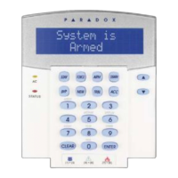
KEYPAD CONNECTIONS
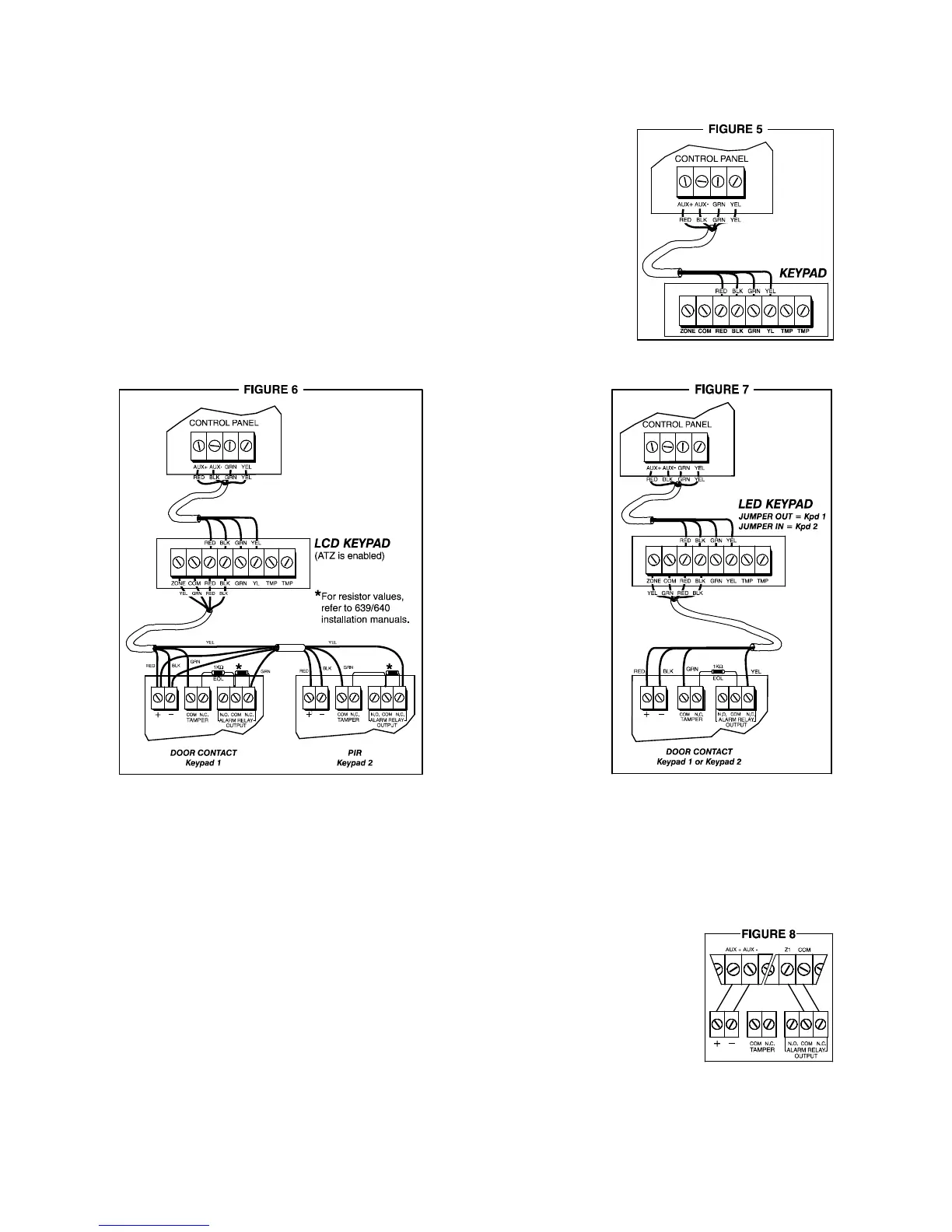
Panel/keypad connection:
The four keypad connections labeled "red", "black", "green" and "yellow"
should be connected to the cor
responding colour terminals on the control
panel PC board.
Keypad zone connection:
The two connections labeled "zone" and "com" are used to connect a
zone to the keypad. Up to 5 keypads may be connected to the control
panel but only two (2) keypad zones (Keypad 1 and Keypad 2) can
be
active at any one time. Examples of keypad zone connection pos
sibilities
(depending on type of keypad used) are shown below:
639/640 LCD keypads 616/626/633 LED keypads
To disable the keypad zone (when keypad zone supervision is deactivated):
616/626: Connect the blue wire “ZONE” to the black wire “COM” and remove EOL jumper 2.
633/639/640: Connect a 1kW resistor between the zone terminal and the com terminal.
ZONE INPUT TERMINALS
The system hardware will recognize the following conditions for each zone:
Single Zone Connections
Note: Keypad zones always use a 1KW EOL resistor.
ZONE connection, without EOL resistor (N.C. contacts)
address 088, key [MEM] = "on"
key [10] = "off" (default)
key [11] = "off" (default)
address 090, key [8] = "off"
8
IM738-738EX
738: without ATZ
Kpd 1 = Zone 7
Kpd 2 = Zone 8
738:
Kpd 1 = Zone 13
Kpd 2 = Zone 14
738 EXPRESS:
Kpd 1 = Zone 8
Kpd 2 = Zone 9
Note: the 640
keypad can be used
with the
738/738EXPRESS
panels but will not
display correct event
list codes.
 Loading...