BLACK
RED
RECHARGEABLE
BATTERY
-
+
COM
AC
AUX
BELL
-+-+
PG1
PG2
N.C. N.0.
BATT
CCCCCC
119531712106428
RED BLK GRN YEL
+
+
+
+
+
+
DIALER
RELAY
BATT
5AMP
OPTION RLY
SERIAL
OUTPUT
SERVICE
KEYPAD
T-1
R-1
TIP
RING
DIALER
BELL
RELAY
PARADOX
SECURITY
SYSTEMS
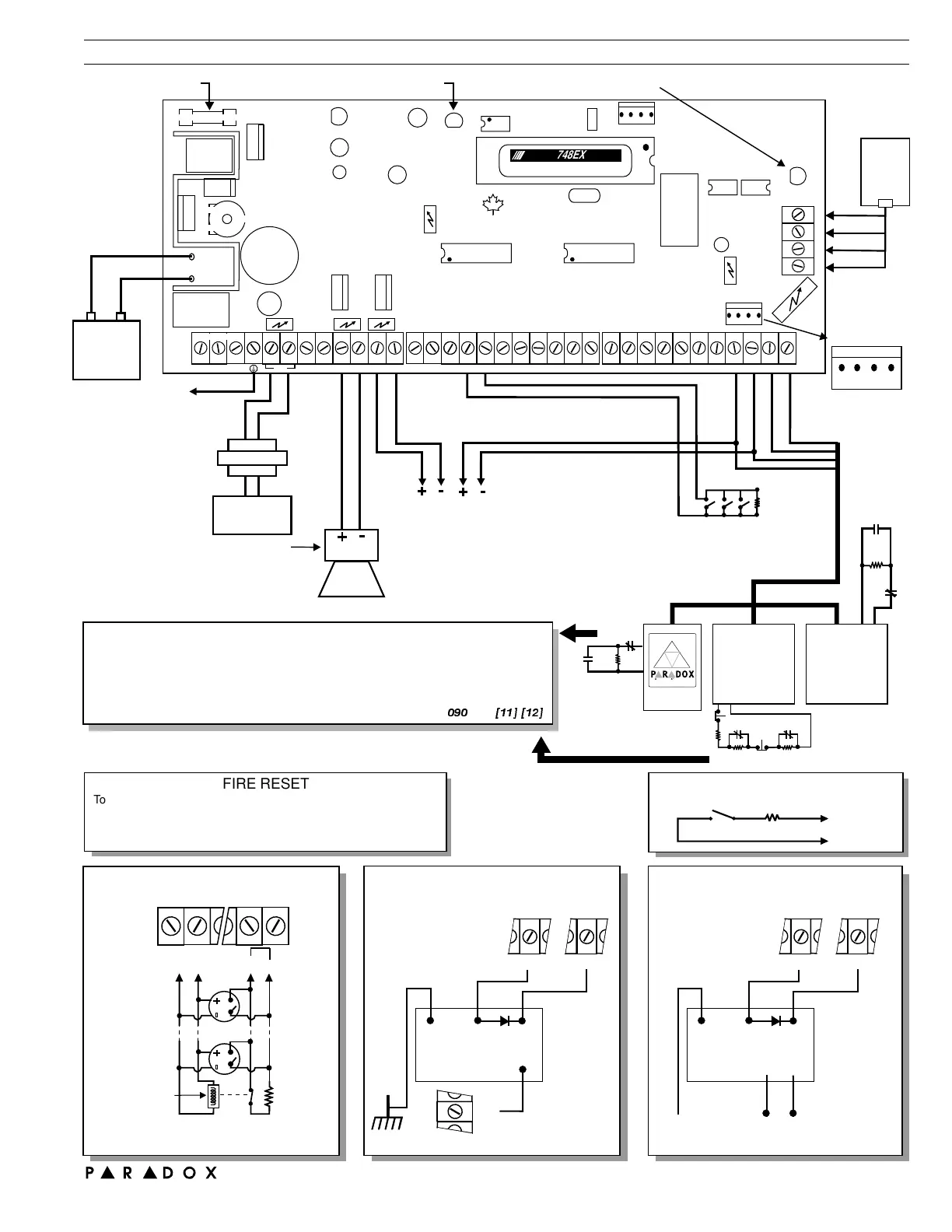
To cabinet and
grounding rod
For zone connections
see diagrams below.
Can be used as
additional aux. power
terminals
-+
-+
AUX POWER 400mAmax.
UL/ULC 250mAmax. for 24 hr.standby.
To connect additional wiring to auxiliary power,
use the red (+) and black (-) keypad connectors.
Aux power will shut down if current exceeds 1A.
BELL OUTPUT
UL/ULC 650mA max.
will shut down if
current exceeds 3A.
BELL
SIREN
-+
TRANSFO
A.C.
POWER
16.5VAC 40VA
Smoke and heat detectors
N.O. contacts
* Zone 3 = Fire zone if
zone definition
is "24 hour".
UL/ULC
12VDC / 7AH
UL: K12 model T16 V4O
ULC: Frost model FTC 1637
EOL
1KΩ
UL/ULC: Wheelock 46T-12
Warning: Improper
connection may result in
damage to the system.
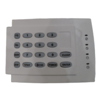
KEYPAD
639/640
MAX 5 per system
KEYPAD
616/626/633
MAX 5 per system
N.C.
N.O.
1K
EOL
Ω
PS1
Keypad
1or2
Keypad
1or2
KEYSWITCH CONNECTION
KEYSWITCH
KYPD GRN
KYPD BLK
220Ω
SECURITY SYSTEMS
N.C.
N.O.
1K
EOL
Ω
*
1K
EOL
Ω
N.C.
N.C.
Keypad 1 Keypad 2
PS1 software version
Keypad software versions prior to
1.1
4.0
Keypad supervision must be OFF
}
PS1 software versions onward
Keypad software versions onward
2.0
4.0
Keypad supervision must be ON
}
*
(See Address , key )
090 [11] [12]
FIRE RESET
To program PGM1 to conduct 4 second smoke detector reset when
and are pressed simultaneously:[ ] [ ]
CLEAR ENTER
Address = (first digit)
Address =
039 [ ]
040 [5] [10]
BYP Address =
Address =
042 [2 ] [6]
056 [10] [10] [4]
ND
FIRE ALARM ZONE CONNECTIONS
* PGM maximum 50mA
Smoke detector
power supervision
relay, 12VDC
COM
Smoke
detector
Smoke
detector
PGM
Z3
AUX
+
1K
EOL
Ω
+
+
-
-
Smoke detector must be 4 wire latching -
UL Falcon model 5454, ULC BRK 2412.
Power supervision relay model MR3-UL.
*
P R DOX
RMED
RE DY
MAX 5
per system
For resistor values,
refer to 639/640
installation manuals.
Keyswitch can be used
in parallel with keypad
(or PS1).
GROUND START CIRCUIT
RNG
WHT
BLK RED
YEL
MR3-UL
+AUX
PGM
WHT
BLK RED
MR3-UL
+AUX
PGM
PGM OUTPUT RELAY
YELBRN
COM N.C. N.O.
780 Industrial Blvd., St-Eustache, Montreal, Quebec, Canada J7R 5V3 Fax: (514) 491-2313 http://www.paradox.ca
Paradox Security Systems Graphic Dept
PRINTED IN CANADA
ESPRIT 748EXPRESS WIRING DIAGRAM
BRN
GRY
GRN
RED
RJ31X
CA 38A
"TLM" LED: Short flash = OK
Long flash = Fault
Warning:
Disconnect
telephone line
before servicing.
Caution: Disconnect
battery before
replacing fuse.
Charging and battery test LED
(every 60 seconds)
OFF = Disabled
Constant = On Line
Four pin connector
canbeusedfor
quick installation of
an Esprit keypad.
Service Keypad
+ AUX
-
GRN YEL
748HS
ESPRIT
748EXPRESS
ESPRIT
 Loading...