ZONE EXPANSION MODULES (SPC-ZX4/8)
The following options and features are only available to program when a Zone Expansion Bus Module has been
connected to the Spectra control panel’s communication bus as shown on page37. The Zone Expansion Modules
provide you with up to 4 (SPC-ZX4) or up to eight (SPC-ZX8) additional hardwired inputs and one normally open
50mA PGM output (on SPC-ZX8 only).
Do not connect more than one Zone Expansion Module.
Bold = Default Setting
PGM TIMER (Zone Module SPC-ZX8 Only)
[655] ___/___/___seconds (000 = follow stop event) PGM1 TIMER (HARDWIRE) 5 sec. (default)
SECTION [650]: Options
Option OFF ON
[1] EOL (end-of-line) Resistors for hardwire modules l No EOL l Use EOL Resistors
[2] Zone Expansion Module Tamper Recognition l Disabled l Z1 becomes tamper input
[3] PGM1 on Zone Expansion Module follows Global
PGM programmed in sections [124] & [125]
l Disabled l Enabled
[4] Future Use l N/A l N/A
[5] Future Use l N/A l N/A
[6] Future Use l N/A l N/A
[7] Future Use l N/A l N/A
[8] Future Use l N/A l N/A
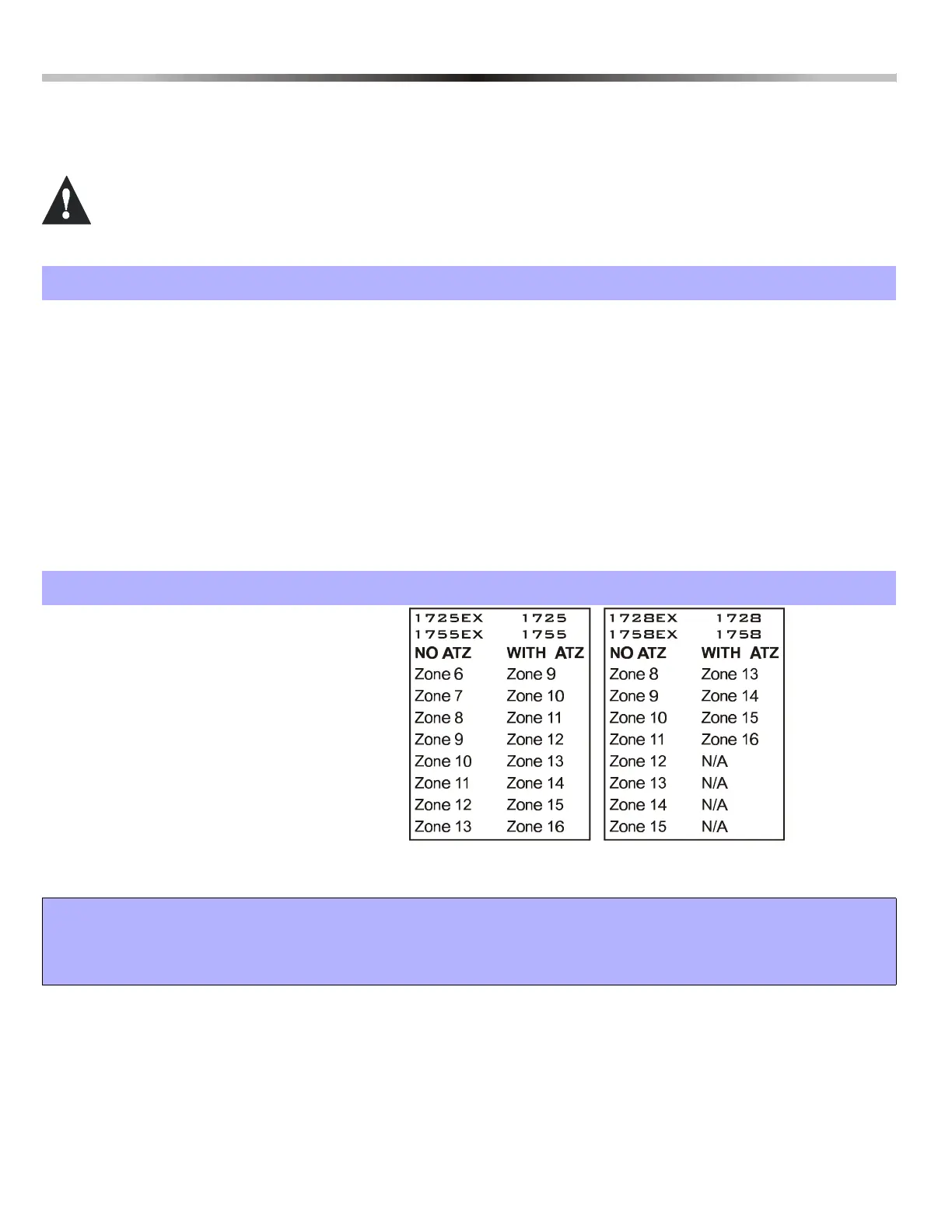
SECTION [651]: Zone Assignment
Option OFF ON
[1] l Disabled l Z1 = Expan. Input 1 =
[2] l Disabled l Z2 = Expan. Input 2 =
[3] l Disabled l Z3 = Expan. Input 3 =
[4] l Disabled l Z4 = Expan. Input 4 =
[5] l Disabled l Z5 = Expan. Input 5 =
[6] l Disabled l Z6 = Expan. Input 6 =
[7] l Disabled l Z7 = Expan. Input 7 =
[8] l Disabled l Z8 = Expan. Input 8 =
WARNING!
Avoid assigning devices from different modules to the same Expansion Input. For example, do not assign a wireless trans-
mitter to section [601], then connect a detection device to Z1 of a hardwire module and enable option [1] in section [651].
This would mean both devices have been assigned to the same Expansion Input.
 Loading...