2 Complete Installation Manual
1: INTRODUCTION
1.1 FEATURES
• 6 Programmable Zones: 4 Zones, 1 Keypad Zone, 1 Fire/24Hr. Burglary Zone
• 1 Installer Code and 8 User Codes (1 System Master and 7 User Codes)
• 2 Programmable Outputs
• Regular Arming, Stay Arming, Force Arming, One-touch Arming, and Bypass Programming
•5A Relay
• Keypad Activated Panic Alarm
1.2 SPECIFICATIONS
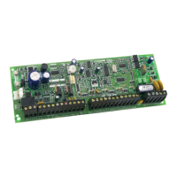
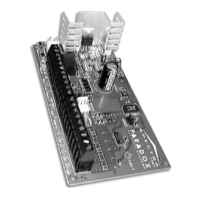
1.2.1 SPECTRA 1727 CONTROL PANEL
AC Power: 16Vac transformer with 20VA rating, 50/60Hz
Battery: 12Vdc, 4Ah
Aux. Power: 12Vdc output, 400 mA max., shutdown at 1A (fused)
Bell Output: 1A, shutdown at 3A (fused)
Battery Output: fused at 5A
PGM1 Output: 50mA maximum, 30mA recommended
PGM2 Output: 50mA maximum, 30mA recommended
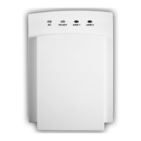
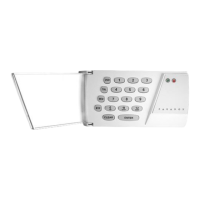
1.2.2 SPECTRA 1686H AND 1686V 10-ZONE LED KEYPADS
Power Input: 9-16Vdc
Zones: 1 Standard Keypad Zone
Current Consumption: 62 to 116mA
1.3 PROGRAMMING METHODS
Use the Programming Guide on page 10 to keep track of how the sections were programmed. We recommend that you read this entire manual
before you begin programming.
1.3.1 SINGLE DIGIT ENTRY METHOD
Single Digit Data Entry is used in sections [10], [11], [12] and [13]. After entering Programming Mode as described in the shaded box
above, in sections [10] to [12] you will enter a Decimal value from 00 to 99 representing seconds and in section [13] you will enter two
single digits each representing a PGM option. The required data will be explained in the respective sections of this manual. Once you
have entered the required data, the control panel will save and exit the section, which returns programming to STEP 3.
1.3.2 MULTIPLE FEATURE SELECT PROGRAMMING METHOD
Multiple Feature Select Programming is used in sections [14], [15], [16], [17], [18], [19], and [20].
For sections
[14], [15], [16], [17], and [18] each key from [1] to [6] represents a zone from [1] to [6].
For sections
[19] and [20] each key from [1] to [8] represents an option.
After entering Programming Mode as described in the shaded box above,
press the key corresponding to the desired zone or option
and the corresponding key will illuminate
†
. This means it is selected. When you press the key again, it will extinguish and it will no longer
be selected. Press the keys as many times as you need to select the desired zones or options. Press the
[
ENTER
]
key to save.
†
patented. See page 15.
2: INSTALLATION
This equipment must be installed and maintained by qualified service personnel only.
2.1 LOCATION AND MOUNTING
Refer to the connection drawing on page 13. Push the four white nylon mounting studs into the back of the cabinet before mounting it to the wall.
Pull all cables into the cabinet and prepare them for connection before attaching the circuit board to the studs. The installation site should be dry,
close to an AC source and ground connection, and not easily accessible to intruders. Leave at least 2" (5cm) around the cabinet to permit
adequate ventilation and heat dissipation.
2.2 EARTH GROUND
Connect the EARTH terminal from the control panel to the cabinet and cold water pipe or grounding rod as required by local electrical codes.
How Do I Enter Control Panel Programming Mode?
STEP 1: Press [ENTER]
STEP 2: Enter your [INSTALLER CODE] (default: 0000/000000)
STEP 3: Enter the 2-digit [SECTION] you wish to program
STEP 4: Enter the required [DATA]
 Loading...