Bulletin HY25-1890-M1/US
Owner’s Manual
10-Bolt Extended Shaft PTOs
Parker Hannifin Corporation
Chelsea Products Division
Olive Branch, MS 38654 USA
8
PTO Pre Installation
Installation Instructions
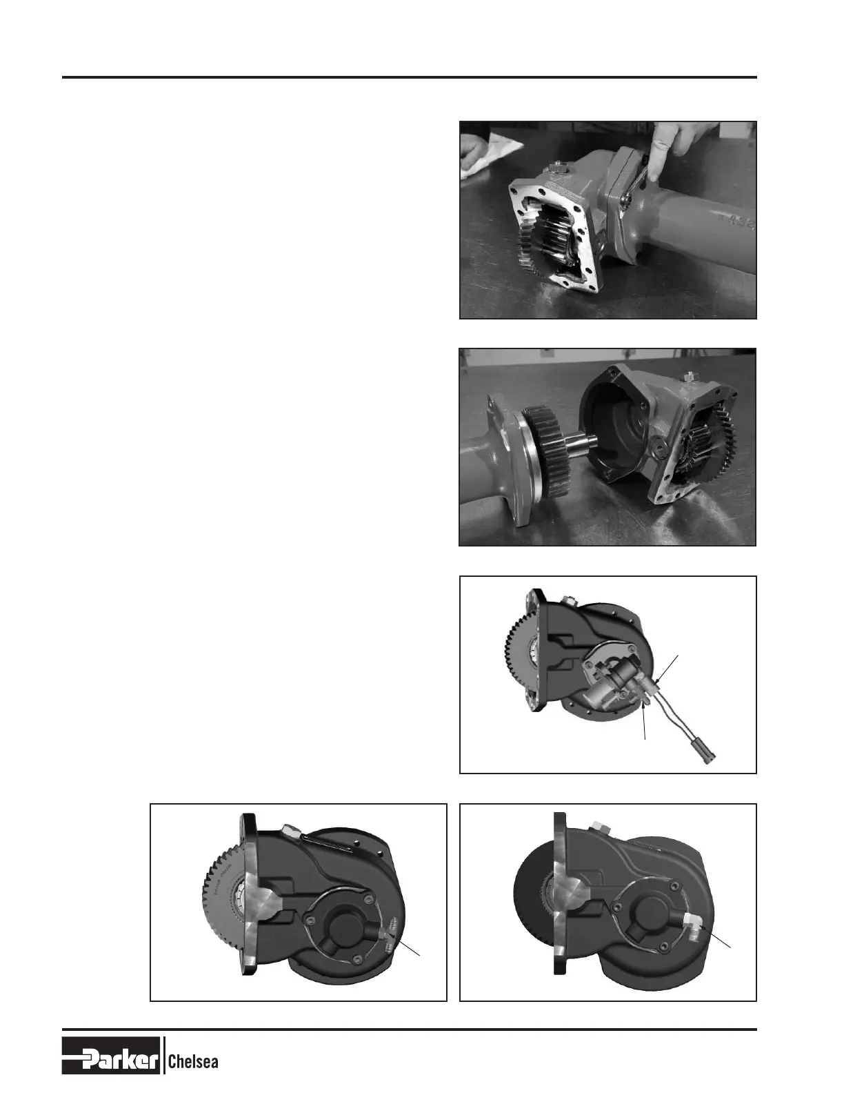
1. At installation, the input housing is installed to the
transmission first. The 890/897 comes from the
factory assembled. Remove the 4 bolts that connect
the tube section to the input housing (Fig. 1).
2. Split the input from the output tube assembly. It will
be tight because of the installed O-Ring seal.
O-Ring must be installed into the O-Ring groove on
the tube pilot shoulder (Fig. 2).
NOTE: If O-Ring is damaged, replace it with the one
supplied with the PTO Unit.
3. Install the fitting (1) into the pressure port on the
valve cap as shown Fig. 3. Torque to 156-180 lbs-in
[18-20 Nm]. Next install the pressure switch
(890 Series Only) (2) into the port in the valve cap
as shown and torque to 120-140 lbs-in [14-16 Nm]
(Fig. 3, 3a, & 3b).
NOTE: See Hose Installation Sketch SK-504
(890/892 Series) on page 20 or SK492/SK-599 (897/899
Series) on page 21.
Fig. 1
Fig. 2
Fig. 3
Fig. 3b After 02/22/16Fig. 3a Prior to 02/19/2016
890/892 Series
(1)
(2)
897/899 Series
(1)
897/899 Series
(1)
 Loading...


