
G
Gina TrevinoAug 14, 2025
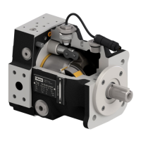
What to do if Parker PV Water Pump drive motor turns and pump turns, but there is no output?
- AasummersAug 14, 2025
If the drive motor and pump are turning, but there's no output, consider these potential causes and solutions: * **Wrong direction of rotation:** Change the direction of motor rotation. * **Fluid reservoir issue:** Fill the reservoir to the required level or increase the suction pipe length if the suction line ends above the fluid level. * **Blocked suction line:** Check the suction line for free flow, open any valves in the suction line (valves should have an electrical indicator), and check the suction filter. * **Suction line leak:** Seal the suction line to prevent air from entering. * **Air in pressure line:** Unload the pressure port, unload the system before starting, and bleed air from the pressure line.