4
Parker Hannifin Manufacturing Germany GmbH & Co. KG
Pump & Motor Division Europe
Chemnitz, Germany
Electro hydraulic proportional controls version 45 for
axial piston pumps, PV series
Bulletin MSG30-3254-INST/UK
Installation and setup manual
S T
M
P1
P
AP
T
AP
T
S
U
Solenoid current,
Displacement
control valve
Solenoid A
Solenoid B
Signal,
displacement
Displacement control valve
Code PVCMD1FBD**
p1
p
A
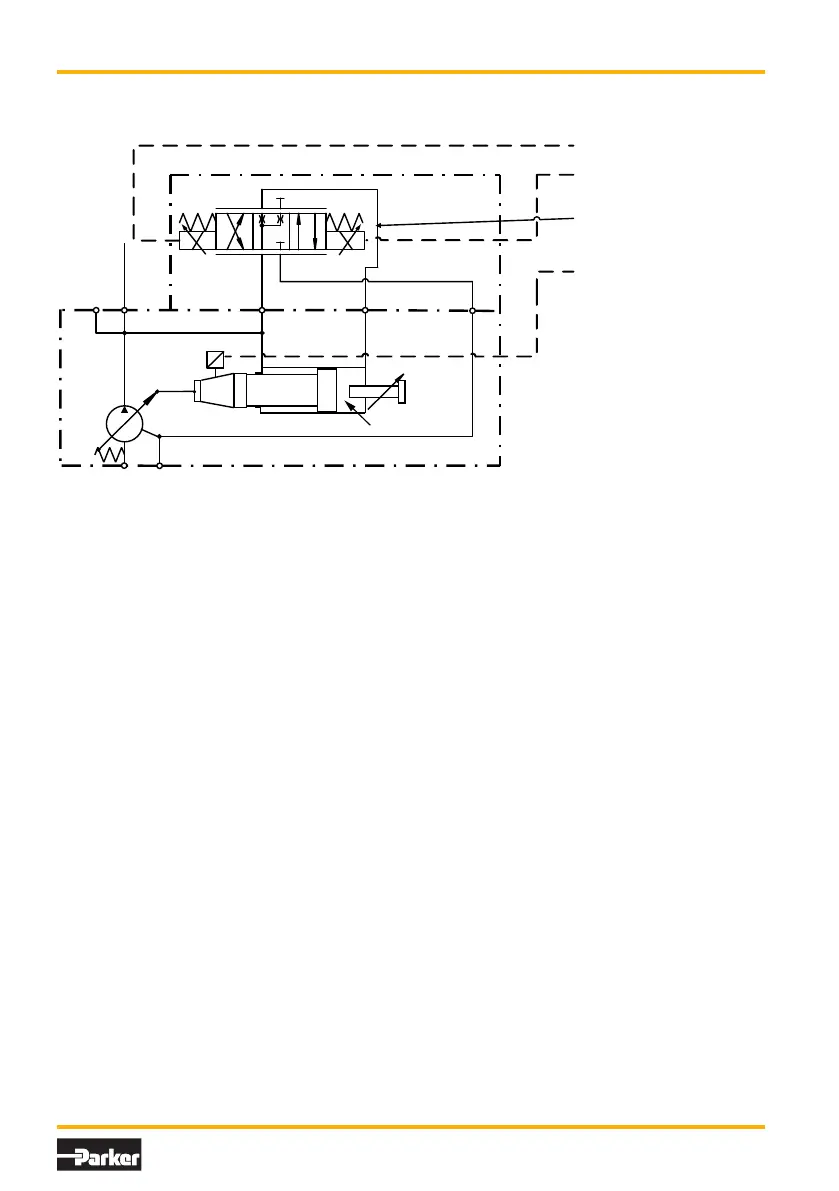
The control valve contains a control spool,
which is moved by two proportional solenoids.
The valves hydraulic neutral point is given by
the electronic control module. According to
the area ratio of the servo piston, the control
pressure p
A
is approximately 25 % of the pump
outlet pressure p1.
Solenoid A is driven by the electronic module for
a flow command of 100 %. The spool connects
thereby port A with the pump housing (Port T).
The oil out of the large piston area drains o,
the pump is swashing to maximum displace-
ment. Solenoid B is activated in case of 0 % flow
command. The pump outlet pressure p1 on the
large servo piston area downstrokes the pump
Figure 2: Circuit diagram...FDV control
FDV - Function
to minimum displacement. This requires a pump
outlet pressure p1 of at least 15 bar.
If this pressure cannot be maintained, special
arrangements for a proper displacement control
are required (please refer to chapter 4). Without
an appropriate load pressure the pump will stay
at full displacement.
The ordering code for a single control valve is:
PVCMD1FB*** the first * indicates the mounting
option ( with interface plate / elbow manifold ).
The two * at the end indicate seal option and
screws option (For details please see the com-
pensator spare parts list PVI-PVC).