18
Parker Hannifin Manufacturing Germany GmbH & Co. KG
Pump & Motor Division Europe
Chemnitz, Germany
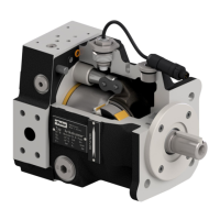
Electro hydraulic proportional controls version 45 for
axial piston pumps, PV series
Bulletin MSG30-3254-INST/UK
Installation and setup manual
9.2 Basic adjustment LVDT
The inductive position transducer for displace-
ment feedback (LVDT) and the compensator
valves are factory preset and the settings are
secured. New or readjustment is only neces-
sary after repair.
LVDT for displacement feedback:
Prior to a basic setting the adjustment of the
armature length is to be checked / readjusted
(see figure 16). The exact dimension for this
setting is given in table 4:
Size Size Serie 45
1 PV016-028 73.5
2 PV032-046 73.5
3 PV063-092 75.0
4 PV140-180 75.0
5 PV270 75.0
6 PV360 75.0
Table 4: setting dimensions LVDT core
Figure 16: Setting dimension A for LVDT armature
The adjustment is secured by a removable glue.
A new setting again has to be secured to avoid
uncontrolled re-setting.
At full upstroked pump the mechanical adjust-
ment can be verified: The voltage at the LVDT
output (pin 25 at the control module) should
have a value as given in the table below (± 0,2 V).
Zero adjustment:
Next the zero adjustment of the LVDT is to be
checked. The LVDT and the solenoid of the
displacement control valve are to be connected
according to chapter 9 to the electronic control
module.
Size voltage size voltage
PV016 6.34 V PV063 7.12 V
PV020 6.06 V PV080 6.48 V
PV023 5.87 V PV092 6.10 V
PV028 5.50 V PV140 5.24 V
PV032 6.40 V PV180 3.83 V
PV040 5.70 V PV270 4.06 V
PV046 5.43 V PV360 4.06 V
Protection plug
with o-seal
Zero adjustment
(sealed)
Do not touch!
electrical
connection
Figure 17: Iinductive positon transducer (LVDT),
outside view
At running pump the command for the displace-
ment is to be set to 0 and the pressure relief valve
of the circuit / test rig has to be set to a pressure
> 25 bar. All other connections / valves in the
hydraulic circuit are to be closed.
The pump then will down stroke to deadhead
at the minimum pump compensating pressure
(10 ± 2 bar). By setting the zero adjustment
potentiometer (see figure 17) at the LVDT the
diagnosis output of the control module is to
be set to 0 V, as the actual displacement is the
minimum displacement that can be controlled.
After adjustment the potentiometer must be
sealed again.
MAX-adjustment:
Next the command for the displacement is to
be increased, until the maximum displace-
ment of the pump is reached. That can either
be monitored by using the diagnosis output or
a flow meter at the pump outlet. The maximum
displacement is reached, if the displacement /
flow does not further increase, even when the
input command is still raised.