12
PWDXXA-40X_20 5715-677 UK.indd 26.01.17
Electronic for proportional DC valves
Series PWDXXA-40X
Operation Manual
Parker Hannifin Corporation
Hydraulics Group
Parker Hannifin Corporation
Hydraulics Group
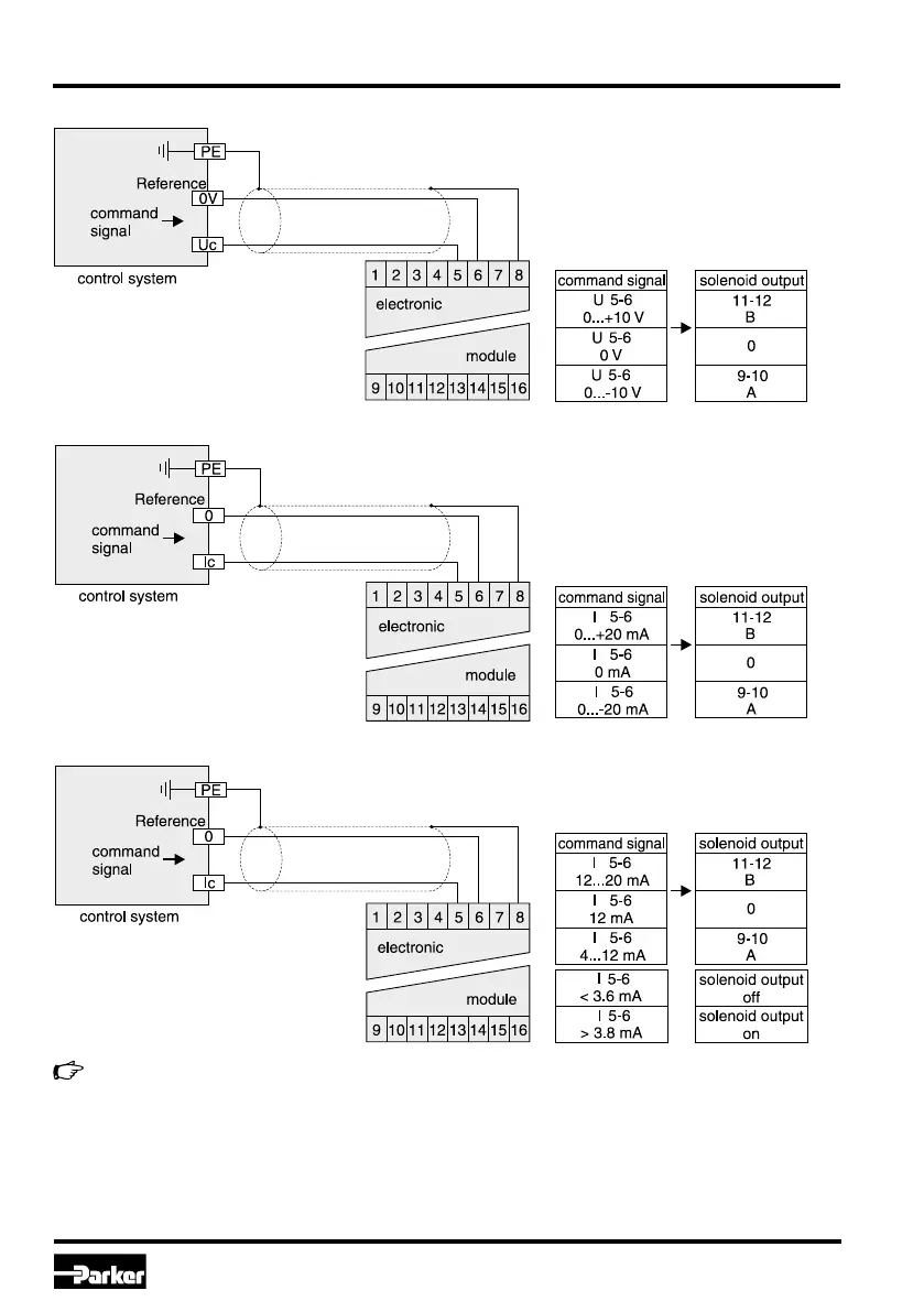
Wiring diagram of voltage command input +10...0...-10 V
Wiring diagram of voltage command input +20...0...-20 mA
Wiring diagram of current input 4...12...20 mA
The option 4...20 mA uses the “0mA” condi-
tion as breakdown-information. This means
the presence of an evaluable failure informa-
tion if the input signal line is interrupted. In
this case the solenoid output will be switched
off. The output will switched on when the input
signal reaches a value of 3.8 mA, it switches
off when the command falls below 3.6 mA.
This determination follows the NAMUR-
specification NE43. If necessary, the com-
mand signal cable break detection can be
disabled by selecting the parameter E19.
NAMUR is an association of users of proc-
ess control technology.

 Loading...